
Improved concrete machining equipment

A technology for processing equipment and concrete, which is applied in clay preparation devices, chemical instruments and methods, cement mixing devices, etc., and can solve problems such as affecting the mixing effect of concrete ratio, cumbersome and complicated structural design, and dead corners of mixing.

Inactive Publication Date: 2018-06-15
莫宇
View PDF4 Cites 0 Cited by
  • Summary
  • Abstract
  • Description
  • Claims
  • Application Information

AI Technical Summary

Problems solved by technology

[0002] In the process of building construction, concrete is a commonly used material. Cement is used as cementitious material, sand and stone are used as aggregate, mixed with water in a certain proportion, and it is obtained after mixing. At present, the structural design of concrete mixing equipment is heavy and complicated. The mechanism is fixed, and there is a mixing dead angle, so that the concrete cannot be fully and evenly mixed, which greatly affects the mixing effect of the concrete.

Method used


Image

  • Improved concrete machining equipment
  • Improved concrete machining equipment
  • Improved concrete machining equipment

Examples


Embodiment Construction

[0014] Combine below Figure 1-Figure 4 The present invention will be described in detail.

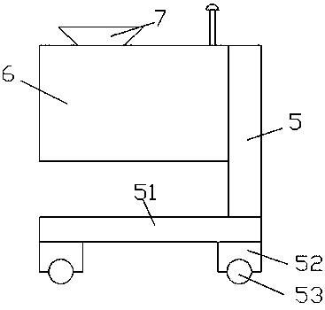
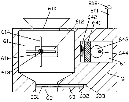
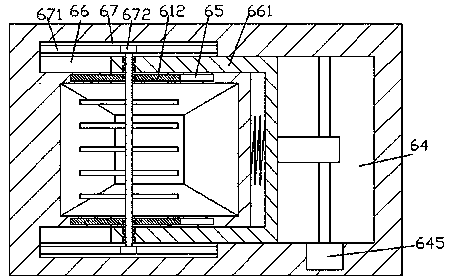
[0015] refer to Figure 1-Figure 4 , an improved concrete processing equipment according to an embodiment of the present invention, comprising a support plate 5 and a base 6 fixedly installed on the left end of the support plate 5, the lower side of the base 6 is provided with a right end and a The support plate 5 is fixedly connected with a fixed bottom plate 51, and a vertical rod 52 is fixed around the bottom end surface of the bottom plate 51, and a rolling wheel 53 is installed in the bottom end surface of the low rod 52. Material chamber 61, a loading bucket 7 is fixed on the top end surface of the base 6 on the upper side of the stirring chamber 61, and the inner top wall of the stirring chamber 61 is provided with a communication setting with the loading bucket 7 The loading chamber 610, the bottom end surface of the base 6 on the lower side of the stirring chamber 61 is prov...


PUM


Abstract

The invention discloses improved concrete machining equipment. The improved concrete machining equipment comprises a supporting plate and a base fixedly arranged at the left end of the supporting plate. A fixing bottom plate which is fixedly connected with the supporting plate is arranged on the lower side of the base, vertical rods are fixedly arranged on the periphery of the bottom surface of the bottom plate, rolling wheels are arranged in the end surface of the bottom of the low rod in a rolling mode, a stirring cavity is formed in the base, a loading hopper is fixedly arranged on the endsurface of the top of the base on the upper side of the stirring cavity, the inner top wall of the stirring cavity is provided with a loading cavity which communicates with the loading hopper, a discharging groove which communicates with the stirring cavity is formed in the bottom end surface of the base at the lower side of the stirring cavity, a driving cavity is formed in the base at the rightside of the stirring cavity, and a sliding connection frame is connected in the drive-in cavity in a sliding fit mode.

Description

technical field [0001] The technical field of building construction of the present invention is specifically an improved concrete processing equipment. Background technique [0002] In the process of building construction, concrete is a commonly used material. Cement is used as cementitious material, sand and stone are used as aggregate, mixed with water in a certain proportion, and it is obtained after mixing. At present, the structural design of concrete mixing equipment is heavy and complicated. The mechanism is fixed, and there is a dead angle for mixing, which makes it impossible to fully and evenly mix the concrete, which greatly affects the proportioning and mixing effect of the concrete. Contents of the invention [0003] The object of the present invention is to provide an improved concrete processing equipment for overcoming the above-mentioned defects in the prior art. [0004] An improved concrete processing equipment according to the present invention include...

Claims


Application Information

Patent Timeline
Patent Type & Authority Applications(China)
IPC IPC(8): B28C5/14
CPCB28C5/0806B28C5/0831B28C5/14
Inventor 莫宇
Owner 莫宇
Learn More