Vacuum perfusion assisting device and vacuum perfusion process

A technology of vacuum infusion and auxiliary device, applied in the field of blade manufacturing, can solve the problems of slow heating speed, waste of labor efficiency, etc.

Active Publication Date: 2018-06-15
JIANGSU GOLDWIND SCI & TECH CO LTD
View PDF10 Cites 1 Cited by
  • Summary
  • Abstract
  • Description
  • Claims
  • Application Information

AI Technical Summary

Problems solved by technology

When the temperature is high, it is necessary to turn on the air conditioner to cool down; and in the current situation where the supply of fan blades is in short supply, the use of the air conditioner to cool down and the heating speed of opening the mold are relatively slow, resulting in a waste of labor efficiency

Method used


Image

  • Vacuum perfusion assisting device and vacuum perfusion process
  • Vacuum perfusion assisting device and vacuum perfusion process
  • Vacuum perfusion assisting device and vacuum perfusion process

Examples


Embodiment Construction

[0026] Like reference numerals refer to like parts throughout.

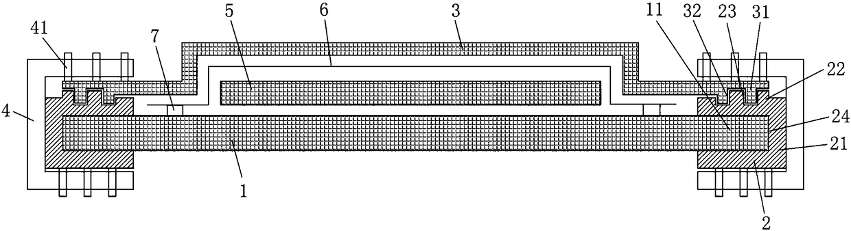
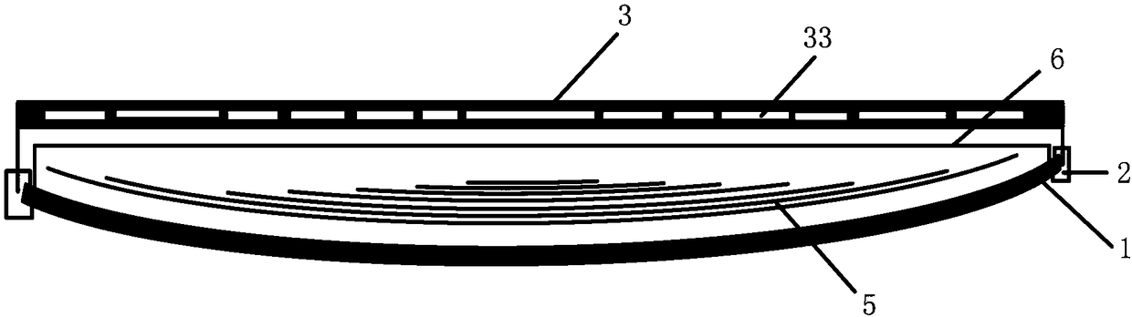
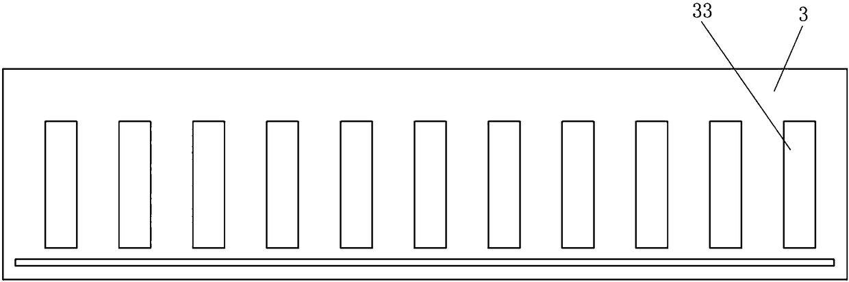
[0027] According to an embodiment of the present invention, a vacuum infusion auxiliary device is provided, which is used to seal the material laying area after laying the laying layer (for example, glass fiber cloth layer) and before vacuuming when manufacturing the blade, so as to A closed environment is formed to facilitate subsequent vacuuming and resin infusion operations.

[0028] The vacuum infusion auxiliary device can be placed on the mold 1 after laying the laying layer or glass fiber cloth layer 5 on the mold 1, and can completely cover the material laying area. The vacuum infusion auxiliary device provided by the present invention can be applied to any blade part molding, for example, blade shell molding, main spar molding or web or other parts molding and so on.

[0029] figure 1 is a schematic structural view of a vacuum perfusion assisting device according to an embodiment of the present inventio...


PUM

PropertyMeasurementUnit
thicknessaaaaaaaaaa

Abstract

The invention discloses a vacuum perfusion assisting device and a vacuum perfusion process. The vacuum perfusion assisting device comprises a flexible main body which can cover a material paving region on a mold, wherein the peripheral edge of the flexible main body is fixed to the mold; a plurality of cavities are formed in the flexible main body; the plurality of cavities can be filled with a fluid medium. Through the vacuum perfusion assisting device and the vacuum perfusion process provided by the invention, the perfusion speed and resin permeation speed during vacuum perfusion of resin can be increased remarkably, the perfusion time is shortened, and the fiber content at different positions after resin curing can be kept consistent.

Description

technical field [0001] The invention relates to the field of blade manufacturing, and more specifically, to a vacuum infusion auxiliary device and a vacuum infusion process. Background technique [0002] Fan blades are usually made of composite materials, mainly including main structures such as shells, main beams, and webs. The above-mentioned main structures are basically composed of glass fiber fabrics and glass fiber reinforced plastics made of resin. The laying process requirements of glass fiber fabrics vary with different structures. Taking the main beam of the blade as an example, the number of layers in the middle is the largest in the length direction, and the number of layers of fiberglass fabric decreases as you go to both sides. There is even a single layer of fiberglass fabric at the edge, so the thickness of the middle part is thicker, and the edge layer is thinner. The cross section is approximately trapezoidal. Then there is the problem of layer effect, th...

Claims


Application Information

Patent Timeline
Patent Type & Authority Applications(China)
IPC IPC(8): B29C70/36
CPCB29C70/36
Inventor 马小军何成智史超锋
Owner JIANGSU GOLDWIND SCI & TECH CO LTD
Why Eureka
Try Eureka