Dust removing device

A technology of dust removal equipment and dust remover, which is applied in the direction of two-part connection device, electrical components, base/housing, etc., which can solve the problems of inconvenient dust removal operation, high power of dust remover, single setting mode of power distribution cabinet, etc., to improve power consumption safety effect

Inactive Publication Date: 2018-06-22
蒲伟生 +14
View PDF6 Cites 7 Cited by
  • Summary
  • Abstract
  • Description
  • Claims
  • Application Information

AI Technical Summary

Problems solved by technology

[0002] Dust collectors are widely used in the field of industrial dust removal. However, due to the high power of industrial dust collectors, some factories are specially equipped with power distribution cabinets for the plug-in power supply of dust collectors. However, these power distribution cabinets have a single setting mode, and their internal conductive The sheet is set relatively outside, so it is easy to be touched by some metal rods and cause electric shock accidents; at the same time, the dust collector needs to move frequently during the dust removal operation, so it is easy to be affected by pulling the power supply line and cause plugging. Loose, resulting in interruption of power supply, which brings great inconvenience to the dust removal operation

Method used


Image

  • Dust removing device
  • Dust removing device
  • Dust removing device

Examples


Embodiment Construction

[0019] All features disclosed in this specification, or steps in all methods or processes disclosed, may be combined in any manner, except for mutually exclusive features and / or steps.

[0020] Any feature disclosed in this specification (including any appended claims, abstract and drawings), unless expressly stated otherwise, may be replaced by alternative features which are equivalent or serve a similar purpose. That is, unless expressly stated otherwise, each feature is one example only of a series of equivalent or similar features.

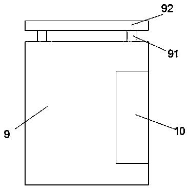
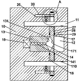
[0021] Such as Figure 1 to Figure 3 As shown, a kind of dust removal equipment of the device of the present invention includes a power distribution cabinet 9 and a plug head 40 connected with the dust remover. The top of the power distribution cabinet 9 is fixedly connected with a dustproof plate 92 through a fixing rod 91. The right side end face of the cabinet 9 is provided with a plug socket 10 that is connected with the plug head 40, and...


PUM


Abstract

The invention discloses a dust removing device. The dust removing device comprises a power distribution cabinet and a latch connected with a dust collector. The top of the power distribution cabinet is fixedly connected with a dustproof plate through a fixing rod. A latch seat is arranged in the right end face of the power distribution cabinet, wherein the latch seat and the latch are matched andconnected. Insertion slots are correspondingly arranged up and down in the latch seat, wherein the ports of the insertion slots face the right. A first sliding slot which horizontally extends is arranged between two insertion slots in the latch seat. A first sliding block is horizontally slidably arranged in the first sliding slot. A screw hole is arranged in the first sliding block, wherein the port of the screw hole faces the left. A screw rod is arranged in the screw hole in a matched manner. The left end of the screw rod is in power connection with a motor fixedly arranged in the inner wall of the left side of the first sliding slot. A second sliding slot which is communicated with the insertion slots is correspondingly arranged in the end wall, which faces the insertion slots, of thefirst sliding slot.

Description

technical field [0001] The invention relates to the technical field of industrial dust removal, in particular to a dust removal device. Background technique [0002] Dust collectors are widely used in the field of industrial dust removal. However, due to the high power of industrial dust collectors, some factories are specially equipped with power distribution cabinets for the plug-in power supply of dust collectors. However, these power distribution cabinets have a single setting mode, and their internal conductive The sheet is set relatively outside, so it is easy to be touched by some metal rods and cause electric shock accidents; at the same time, the dust collector needs to move frequently during the dust removal operation, so it is easy to be affected by pulling the power supply line and cause plugging. If it becomes loose, the power supply will be interrupted, which will bring great inconvenience to the dust removal operation. Contents of the invention [0003] Aim...

Claims


Application Information

Patent Timeline
Patent Type & Authority Applications(China)
IPC IPC(8): H01R13/703H01R13/639H01R13/52H01R24/00
CPCH01R13/703H01R13/52H01R13/639H01R24/00
Inventor 蒲伟生刘品昌段爱霞王宠娟杨飞璐李东风申楠楠崔筱翊朴春玉嵇邵坤周威吕克温宋井领何净东刘平平
Owner 蒲伟生
Why Eureka
Try Eureka