
Novel plugging device for household appliance power supplying

A technology for plug-in devices and home appliances, which is applied to the components, coupling devices, circuits and other directions of connecting devices, can solve problems such as electric shock accidents, potential safety hazards of power supply sockets, and unstable states, and achieve high safety in electricity consumption and reduced safety. Hidden danger, stable operation effect

Inactive Publication Date: 2018-06-29
韦文生
View PDF3 Cites 0 Cited by
  • Summary
  • Abstract
  • Description
  • Claims
  • Application Information

AI Technical Summary

Problems solved by technology

[0002] In modern homes, as the number of home appliances continues to increase, the power supply base also increases. The traditional power supply base is generally only fixedly installed on the wall. The traditional power supply base will be equipped with slots connecting the outside, and the interior and the city. The power supply copper pieces that are electrically connected are generally directly exposed in the slots. Due to children’s curiosity, they will use metal rods to insert into the slots. When the metal rods are inserted, they will directly contact the power supply copper pieces, so it will An electric shock accident occurs, therefore, the traditional power supply stand has a great potential safety hazard; and when the traditional power supply stand cooperates with the power supply plug, it only relies on the clamping of the power supply sheet to maintain the power supply state, but this state is not stable enough. Be careful when you touch the power supply plug or the power supply line, it will cause the power supply plug to loosen or fall off. Therefore, it will cause unexpected power failure and easily affect the home appliances.

Method used


Image

  • Novel plugging device for household appliance power supplying
  • Novel plugging device for household appliance power supplying
  • Novel plugging device for household appliance power supplying

Examples


Embodiment Construction

[0023] All features disclosed in this specification, or steps in all methods or processes disclosed, may be combined in any manner, except for mutually exclusive features and / or steps.

[0024] Any feature disclosed in this specification (including any appended claims, abstract and drawings), unless expressly stated otherwise, may be replaced by alternative features which are equivalent or serve a similar purpose. That is, unless expressly stated otherwise, each feature is one example only of a series of equivalent or similar features.

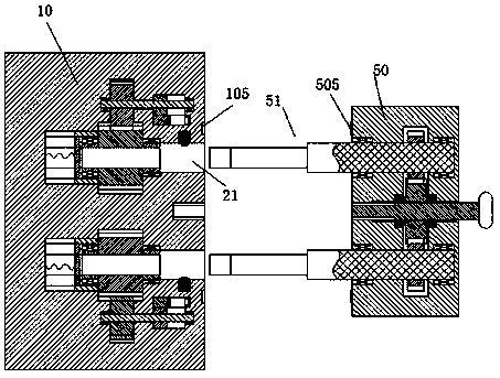
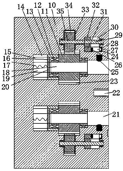
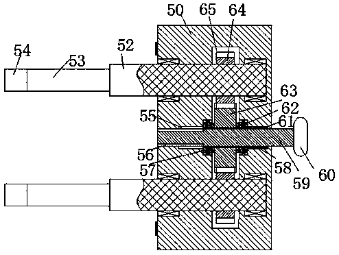
[0025] Such as Figure 1 to Figure 5As shown, a new plug-in device for power supply of household appliances in the device of the present invention includes a power supply stand 10 fixedly installed in the wall and a plug 50 connected to the electrical appliance. The insertion post 51 includes a conductive post 52 connected from right to left, a clamping post 53 and a push post 54, and the plug 50 is symmetrically provided with a first rotatio...


PUM


Abstract

The invention discloses a novel plugging device for household appliance power supplying. The novel plugging device comprises a power supply seat fixedly mounted in a wall and a plug connected with a household appliance, wherein plugging columns are symmetrically arranged in the plug up and down; the plugging columns comprise conductive columns, clamping columns and pushing columns which are connected from right to left; first rotating slots with leftward openings are symmetrically formed in the plug up and down; a first mounting slot which extends up and down and penetrates through the first rotating slots is also formed in the plug; the right ends of the conductive columns are mounted in the first rotating slots in a rotatable manner; a first driven gear fixedly connected with the conductive columns is mounted in the first mounting slot; a first rotating sleeve and a second rotating sleeve are respectively mounted in the left and right end walls of the center of the mounting slot in arotatable manner; a first driving gear meshed with the first driven gear is fixedly connected between the first rotating sleeve and the second rotating sleeve; a left-right connected center slot is formed in the center of the plug; spline slots extending left and right are formed in the centers of the first driving gear, the first rotating sleeve and the second rotating sleeve.

Description

technical field [0001] The invention relates to the field of electric power for household appliances, in particular to a new plug-in device for power supply of household appliances. Background technique [0002] In modern homes, as the number of home appliances continues to increase, the number of power supply sockets also increases. Traditional power supply sockets are generally only fixedly installed on the wall. Traditional power supply sockets are equipped with slots connecting the outside, and the interior and the market The power supply copper pieces that are electrically connected are generally directly exposed in the slots. Due to children’s curiosity, they will use metal rods to insert into the slots. When the metal rods are inserted, they will directly contact the power supply copper pieces, so it will An electric shock accident occurs, therefore, the traditional power supply stand has a great potential safety hazard; and when the traditional power supply stand coo...

Claims


Application Information

Patent Timeline
IPC IPC(8): H01R13/639H01R13/629H01R13/642
CPCH01R13/639H01R13/629H01R13/642
Inventor 韦文生
Owner 韦文生
Features
  • Generate Ideas
  • Intellectual Property
  • Life Sciences
  • Materials
  • Tech Scout
  • Unparalleled Data Quality
  • Higher Quality Content
  • 60% Fewer Hallucinations
Learn More