
Injection device

An injection device, sliding installation technology

Inactive Publication Date: 2018-07-03
HONG FU JIN PRECISION IND (SHENZHEN) CO LTD +1
View PDF4 Cites 0 Cited by
  • Summary
  • Abstract
  • Description
  • Claims
  • Application Information

AI Technical Summary

Problems solved by technology

When the piston is pressed down, the space will be squeezed, and the gas cannot be discharged due to the good airtightness between the piston and the needle tube
As the piston continues to press down, the volume of the space will continue to decrease, resulting in an increase in air pressure, which in turn requires a greater force to push the piston, which is inconvenient for people to use

Method used


Image

  • Injection device
  • Injection device
  • Injection device

Examples


Embodiment Construction

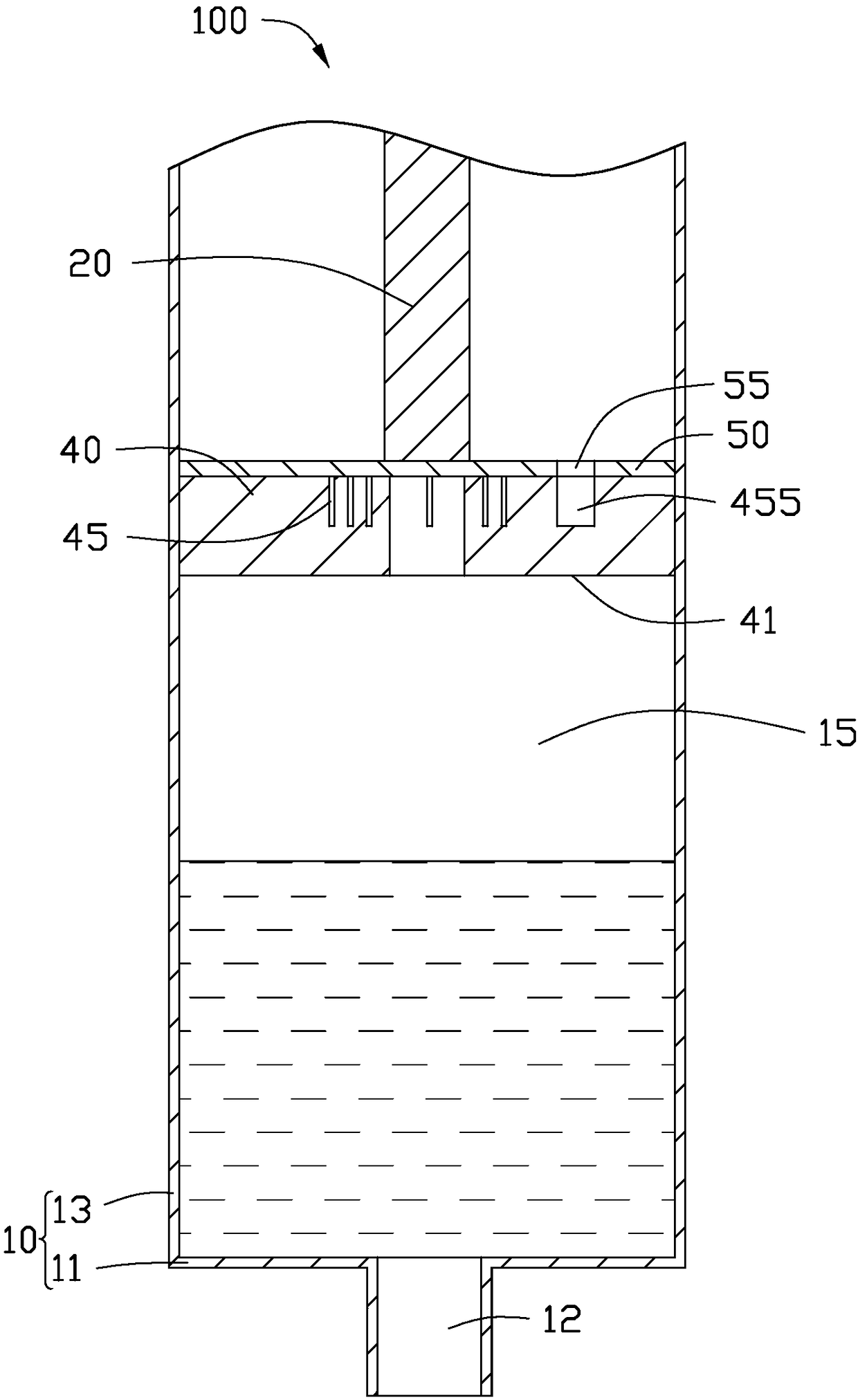
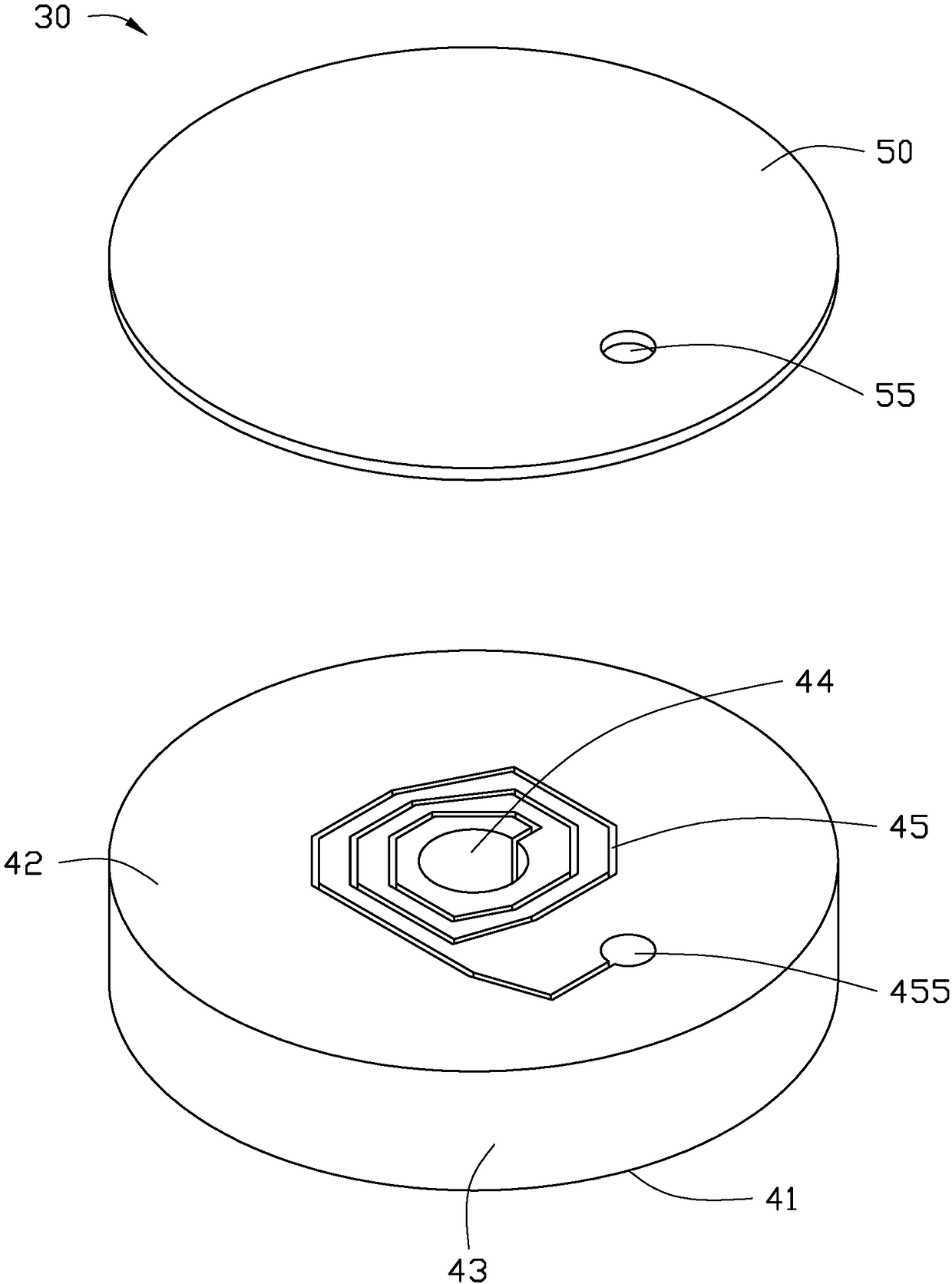
[0025] see figure 1 , In a preferred embodiment of the present invention, an injection device 100 includes a needle tube 10, a push rod 20 mounted on the needle tube 10 and capable of sliding in the needle tube 10, and a push rod 20 fixed on the needle tube 20 Piston 30 at one end. The injection device 100 is used for injecting a fluid. In one embodiment, the fluid may be a liquid with a relatively high viscosity. Further, the fluid may be a liquid such as vegetable oil, honey, or glycerin.

[0026] The needle tube 10 is substantially cylindrical and includes a bottom wall 11 and a side wall 13 surrounding the bottom wall 11 and vertically connected to the bottom wall 11 . The bottom wall 11 and the side wall 13 jointly define a storage space 15 for storing liquid, and the push rod 20 and the piston 30 are slidably installed in the storage space 15 . The bottom wall 11 is provided with a needle hole 12 , and the fluid in the receiving space 15 can be discharged from the need...


PUM


Abstract

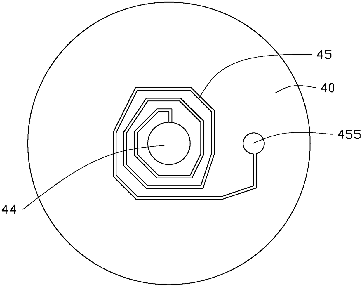
The invention relates to an injection device which comprises a syringe, a push rod arranged in the syringe in a sliding way and a piston fixed at one end of the push rod, wherein the piston comprisesa body and an upper cover, a through hole and an exhaust passage communicated with the through hole are formed in the body, the upper cover is fixed on the body to shield the through hole and the exhaust passage, and a vent hole communicated with one end of the exhaust passage is formed in the upper cover, so as to be convenient for gas to be discharged by passing through the piston.

Description

technical field [0001] The invention is applied in the field of food printing, and in particular relates to an injection device used in the food printing process. Background technique [0002] At present, when the injection device is used to inject food such as fluid into the food capsule, there is generally a space between the piston and the fluid in the needle tube, and a small amount of gas stays in the space. When the piston is pressed down, the space will be squeezed, and the gas cannot be discharged due to the good airtightness between the piston and the needle tube. As the piston continues to press down, the volume of the space will continue to decrease, resulting in an increase in air pressure, which requires greater force to push the piston, which brings inconvenience to people's use. Contents of the invention [0003] In view of the above, it is necessary to provide an injection device that facilitates gas discharge. [0004] An injection device, comprising a n...

Claims


Application Information

Patent Timeline
Patent Type & Authority Applications(China)
IPC IPC(8): A23P20/25
CPCB65D83/0005B65D2205/04B65D83/0022B05B11/0039
Inventor 毛庆宜
Owner HONG FU JIN PRECISION IND (SHENZHEN) CO LTD
Learn More