Rapid installation type anti-freezing faucet

A quick-installation and water nozzle technology, which is applied in the direction of valve device, valve operation/release device, function valve type, etc., can solve the problems of seepage pool, short service life of water nozzle, waste of energy, poor safety and stability, etc. , to achieve the effect of filling the gap in the market, convenient water use and quick installation

Pending Publication Date: 2018-07-20
唐山开丰卫浴用品有限公司
View PDF0 Cites 0 Cited by
  • Summary
  • Abstract
  • Description
  • Claims
  • Application Information

AI Technical Summary

Problems solved by technology

The most common type is the emptying type faucet. Its working principle is to discharge the residual water in the standpipe into the underground seepage pool after closing the valve core. This kind of antifreeze faucet needs to dig a deep pit for pre-buried, and needs to use cement and bricks. Construction materials such as sand and gravel require professional construction work and plumbing work at the same time, which is time-consuming and labor-intensive, with a large amount of work; the service life of seepage pools and water nozzles is very short, and secondary construction is required once problems occur
The other is to rely on heat preservation, electric heating, etc. to achieve the purpose of antifreeze, which is extremely poor in safety and stability, which not only wastes energy, but also increases capital investment.

Method used


Image

  • Rapid installation type anti-freezing faucet
  • Rapid installation type anti-freezing faucet
  • Rapid installation type anti-freezing faucet

Examples


Embodiment Construction

[0027] The present invention will be further described below in conjunction with the accompanying drawings and embodiments.

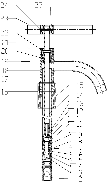
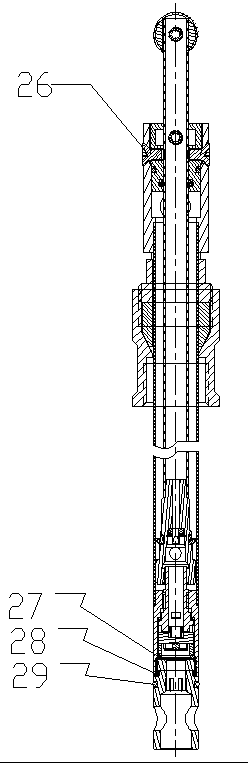
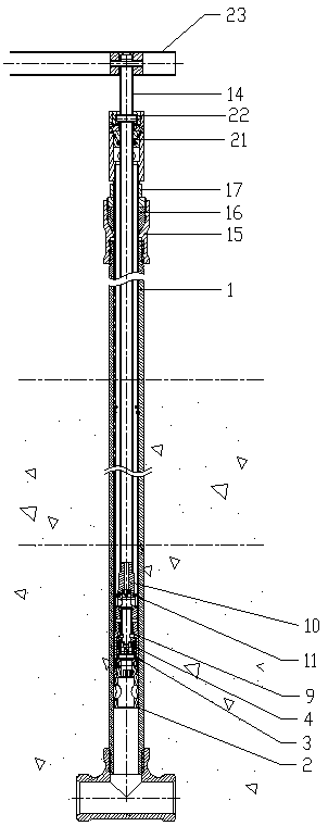
[0028] See attached Figure 1-8 , the quick-installed freeze-free faucet disclosed in the present invention includes a locking joint 2, a fixed tile 3, a moving tile 4, a wear ring 5, a fixed seat 6, a fixed pipe 7, a friction ring 8, an outer Tooth rotating rod 9, inner tooth joint 10, leather cup 11, retaining ring 12, one-way valve 13, lifting inner tube 14, fixed connection nut 15, rubber sleeve 16, lock nut 17, spout 18, V-shaped seal Rubber ring 19, O-ring 20, guide positioning joint 21, elastic pin 22, handle 23, elastic pin 24, handle joint 25, screw 26, O-ring 27, O-ring 28, O-ring 29.

[0029] The pre-embedded pipeline 1 is set at the installation position of the water pipe in advance, and the fixed pipe 7 is inserted into the pre-embedded pipeline 1 . Lock joint 1 is installed in the lower end of fixed pipe 7, and the interior of the lower ...


PUM


Abstract

The invention discloses a rapid installation type anti-freezing faucet. A valve core is of a pipeline structure with water feeding from the lower portion and discharging from the upper portion; the lower portion of an outer tooth rotation rod is connected with a movable ceramic chip through a convex groove structure; the upper portion of a fixed seat is welded to the lower portion of a fixed pipe;a lifting inner pipe is arranged in the fixed pipe; an inner tooth connector is welded to the lower end of the lifting inner pipe and internally provided with a one-way valve, and the inner tooth connector is in clearance fit with an outer tooth on the upper portion of the outer tooth rotation rod; a locking nut and a fixing connection nut sleeve the upper middle portion of the fixed pipe; a clearance is formed between the lower portion of the fixing connection nut and the fixed pipe; and the upper end of a pre-buried pipeline is inserted into the clearance and connected with an internal thread of the fixing connection nut. According to the rapid installation type anti-freezing faucet, the effects that water is conveniently used outdoors in winter, and the pipeline and the faucet are freeof freezing and cracking are ensured, engineering construction is not needed, the market vacancy is filled in, no energy source is wasted, the situation that heat is preserved by consuming energy isavoided, professional staff construction is not needed, installation, maintenance and replacement can be achieved only through a simple tool, installation is rapid, and maintenance is convenient and fast.

Description

technical field [0001] The invention relates to an outdoor anti-freezing faucet, in particular to a quick-installed non-freezing faucet. Background technique [0002] There are more and more types of similar antifreeze products on the market. The most common type is the emptying type faucet. Its working principle is to discharge the residual water in the standpipe into the underground seepage pool after closing the valve core. This kind of antifreeze faucet needs to dig a deep pit for pre-buried, and needs to use cement and bricks. Building materials such as sand and gravel require professional construction work and plumbing work at the same time, which is time-consuming and labor-intensive, and the project volume is large; the service life of seepage tanks and water nozzles is very short, and secondary construction is required once problems occur. The other is to rely on heat preservation, electric heating, etc. to achieve the antifreeze purpose, which has poor safety and ...

Claims


Application Information

Patent Timeline
IPC IPC(8): F16K3/314F16K3/30F16K3/34F16K15/00F16K27/04F16K31/60
CPCF16K3/30F16K3/314F16K3/34F16K15/00F16K27/04F16K31/60
Inventor 金军海
Owner 唐山开丰卫浴用品有限公司
Why Eureka
Try Eureka