
A shock-absorbing bridge structure

A technology of bridge structure and shock-absorbing support, which is applied to bridges, bridge construction, bridge parts, etc., can solve the problems of improving the shock-absorbing support, reducing the transmission acceleration, and the inability of the shock-absorbing support to reach an appropriate height, so as to improve the stability , Improve the effect of shock absorption

Active Publication Date: 2019-07-23
QIJIAN GRP CO LTD
View PDF5 Cites 0 Cited by
  • Summary
  • Abstract
  • Description
  • Claims
  • Application Information

AI Technical Summary

Problems solved by technology

[0003] In actual use, earthquakes, wind vibrations and other equipment vibrations may cause the vibration of the bridge building structure itself, which may lead to the accumulation of damage to the structure. Due to the limitation of its own material and structure, when the seismic vibration changes, the height of the shock-absorbing support cannot be adjusted properly. Increase the height of the shock-absorbing support and increase the natural vibration period of the shock-absorbing support to reduce the vibration The transmission acceleration of the vertical force in the seismic support, so that the peak time period of force transmission is located on the shock-absorbing support and is not transmitted to the bridge deck, thereby reducing the possibility or degree of damage to the bridge deck, otherwise it is easier to cause Damage to bridge columns or bridge decks may even easily lead to bridge fracture

Method used


Image

  • A shock-absorbing bridge structure
  • A shock-absorbing bridge structure
  • A shock-absorbing bridge structure

Examples


Embodiment Construction

[0035] The present invention will be described in further detail below in conjunction with the accompanying drawings.

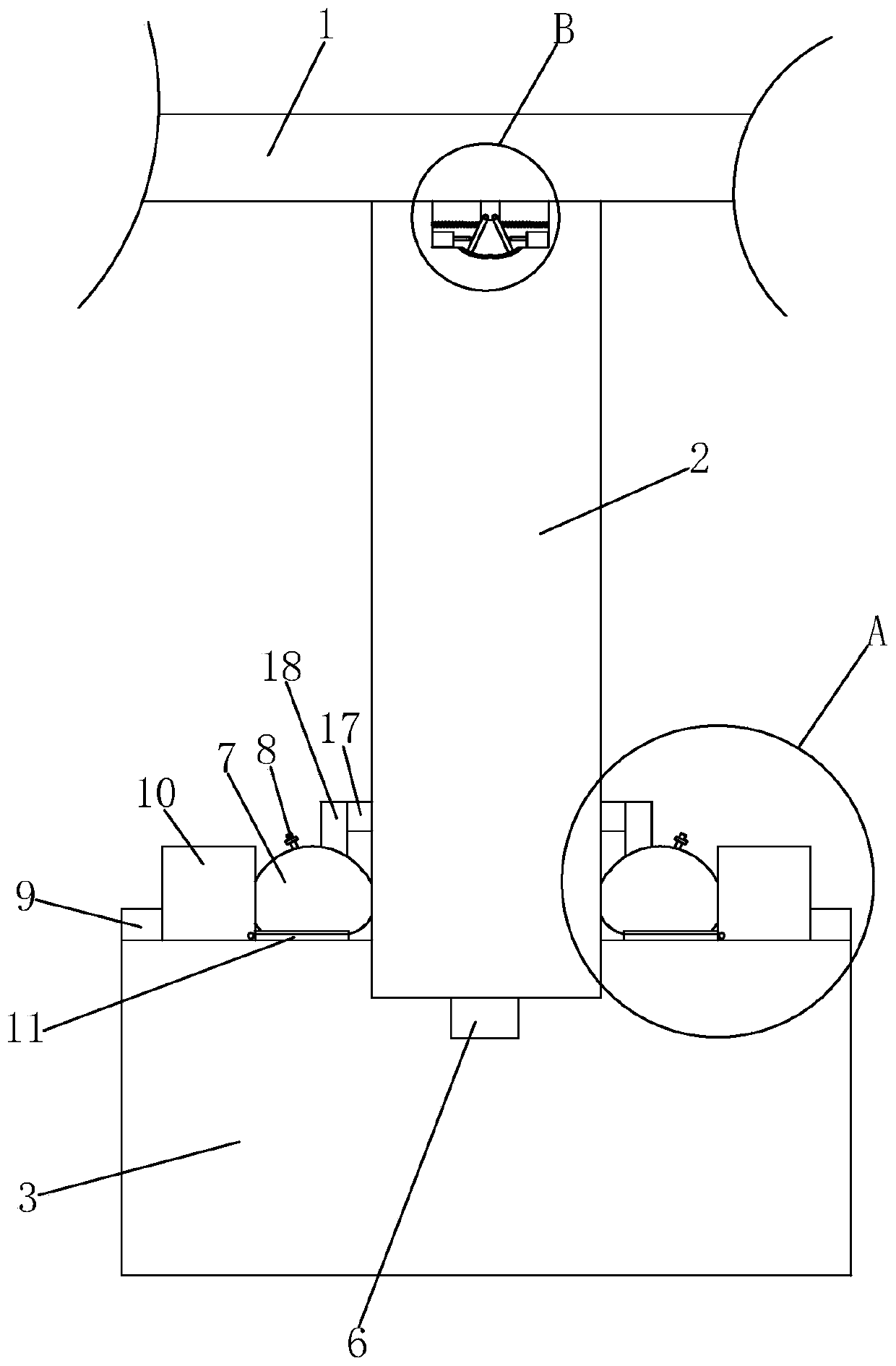
[0036] A kind of shock-absorbing bridge structure, refer to figure 1 As shown, it includes bridge deck 1, bridge column 2 and bridge pier 3.

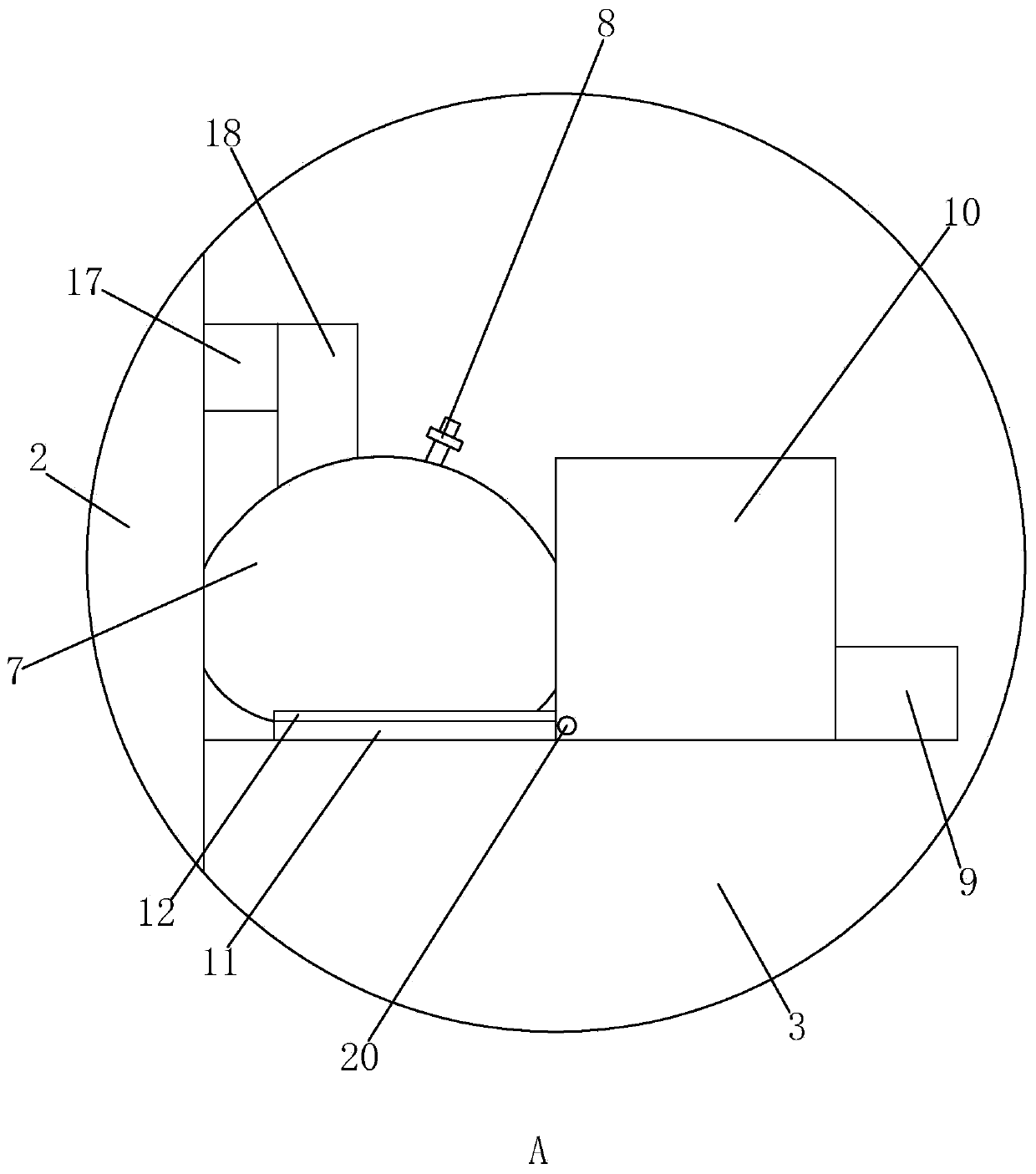
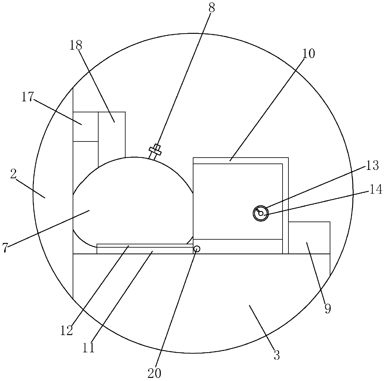
[0037] Among them, refer to figure 1 and Figure 4 As shown, between the bridge deck 1 and the bridge column 2, there is a shock absorber 4 for reducing the force in the vertical direction. The shock absorber 4 belongs to the rubber bearing, and the shock absorber 4 includes a Mounting block 41 , the bottom end of mounting block 41 is rotated by first hinge shaft 19 to be provided with two rotating brackets 42 , and the two rotating brackets 42 are arranged symmetrically.

[0038] The top of the bridge column 2 is provided with an abutting groove 21 for the rotation of the rotating bracket 42 below the mounting block 41. The abutting groove 21 is a part drawn as a circle with the first hinge shaft 19 as the center o...


PUM


Abstract

The invention relates to bridge construction, and particularly discloses a damping bridge structure. The damping bridge structure comprises a deck, bridge posts and bridge piers, wherein a damping support for reducing a force in a vertical direction is arranged between the deck and each bridge post; each damping support comprises a mounting block and two rotating supports; each mounting block is abutted to the deck; the two rotating supports of each damping support are symmetrically and rotatably mounted on the corresponding mounting block and are abutted to the corresponding bridge post; an abutting groove which is used for rotation of the corresponding rotating supports is formed in each bridge post and positioned below the corresponding rotating supports; a driving piece which is used for driving the corresponding rotating supports to rotate along the corresponding abutting groove to change the heights of the corresponding rotating supports in the vertical direction is arranged in each bridge post; a first pressure sensor for measuring the force of the corresponding bridge post in the vertical direction is arranged between each bridge pier and the corresponding bridge post; andeach bridge post is provided with a controller which is electrically connected with the corresponding driving piece and the corresponding first pressure sensor. According to the technical scheme, thedamping bridge structure has the advantage of improvement of a damping effect, and bridge stability is improved.

Description

technical field [0001] The invention relates to bridge construction, in particular to a shock-absorbing bridge structure. Background technique [0002] As one of the earthquake-prone countries in my country, the seismic performance of bridges has become an important part of bridge design. Among them, shock absorption technology is a mature, reliable and effective technology that can improve structural seismic performance and reduce earthquake hazards. It is being increasingly used in various new construction, renovation and expansion, and reinforcement projects. [0003] In actual use, earthquakes, wind vibrations and other equipment vibrations may cause the vibration of the bridge building structure itself, which may lead to the accumulation of damage to the structure. Due to the limitation of its own material and structure, when the seismic vibration changes, the height of the shock-absorbing support cannot be adjusted properly. Increase the height of the shock-absorbing s...

Claims


Application Information

Patent Timeline
Patent Type & Authority Patents(China)
IPC IPC(8): E01D1/00E01D19/04
CPCE01D1/00E01D19/048
Inventor 邵祝青叶舒谷杜效诚张千聪王达光
Owner QIJIAN GRP CO LTD
Learn More