Method for aligning and adhering oil duct struts

An oil channel and bonding technology, applied in the field of aligning and bonding oil channel stays, can solve problems such as slow speed, achieve the effect of mechanization and improve production efficiency

Inactive Publication Date: 2018-07-27
HENAN MECHANICAL & ELECTRICAL VOCATIONAL COLLEGE
View PDF4 Cites 2 Cited by
  • Summary
  • Abstract
  • Description
  • Claims
  • Application Information

AI Technical Summary

Problems solved by technology

[0003] The technical problem to be solved by the present invention is that when bonding the oil passage stays, it is slow to use manual identification of wide sides and thick sides; in order to solve the above problems, the present invention provides a method for aligning and bonding oil passage stays. In the mechanization of bonding oil passage stays, the oil passage stays that are not thick and radially consistent with the rollers are rolled at a certain angle to achieve consistent and correct placement of each oil passage stay

Method used


Image

  • Method for aligning and adhering oil duct struts
  • Method for aligning and adhering oil duct struts

Examples


Embodiment 1

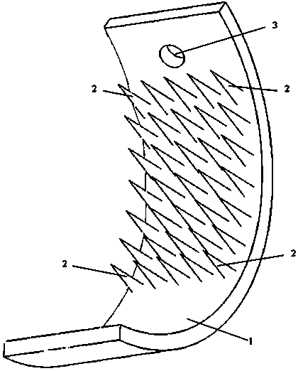
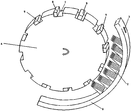
[0038] When the roller tile 1 is assembled with the roller 4, the distance from the tile body 6 to the central axis of the roller 4 decreases sequentially from top to bottom, and the turning device 2 is conical, and from top to bottom, the conical tip reaches the outer surface of the roller 4 The distance also decreases sequentially. Oil passage stays are 6mm wide and 5mm thick. The maximum distance from the conical tip to the outer surface of the roller 4 is 1 mm, and the minimum distance is 0 mm. Roller grooves 7 parallel to the central axis are evenly distributed on the outer surface of the roller 4, and oil passage stays 5 are housed in the roller grooves 7. On the side where the roller 4 rotates downward, the oil passage stay 5 whose thick side is radially consistent with the roller 4 does not touch the convex point and passes through smoothly, and the oil passage stay whose thick side is not consistent with the radial direction of the roller 4 The part of the bar 5 pro...

Embodiment 2

[0040]When the roller shoe 1 is assembled with the roller wheel 4, the distance from the tile body 6 to the center axis of the roller wheel 4 decreases sequentially from top to bottom, and the turning device 2 is barb-shaped, with the top point upward; The distance of the outer surface of the roller 4 also decreases successively. The oil passage stay is 5.7mm wide and 5.2mm thick. The maximum distance from the barbed top to the outer surface of the roller 4 is 0.5 mm, and the minimum distance is 0 mm. Roller grooves 7 parallel to the central axis are evenly distributed on the outer surface of the roller 4, and oil passage stays 5 are housed in the roller grooves 7. On the side where the roller 4 rotates downward, the oil passage stay 5 whose thick side is radially consistent with the roller 4 does not touch the convex point and passes through smoothly, and the oil passage stay whose thick side is not consistent with the radial direction of the roller 4 The part of the bar 5 ...

Embodiment 3

[0042] When the roller shoe 1 is assembled with the roller 4, the distance from the tile body 6 to the central axis of the roller 4 decreases sequentially from top to bottom, and the turning device 2 is hemispherical; from top to bottom, the hemispherical top reaches the outer surface of the roller 4 The distance also decreases sequentially. Oil channel stays are 6.2mm wide and 4.6mm thick. The maximum distance from the barbed top to the outer surface of the roller 4 is 1.3 mm, and the minimum distance is 0 mm. Roller grooves 7 parallel to the central axis are evenly distributed on the outer surface of the roller 4, and oil passage stays 5 are housed in the roller grooves 7. On the side where the roller 4 rotates downward, the oil passage stay 5 whose thick side is radially consistent with the roller 4 does not touch the convex point and passes through smoothly, and the oil passage stay whose thick side is not consistent with the radial direction of the roller 4 The part of ...


PUM


Abstract

The invention discloses a method for aligning and adhering oil duct struts. The method comprises the following specific steps: (1) grooving, namely forming roller grooves used for placing oil duct struts in outer side faces of rollers at intervals, and mounting the oil duct struts in the roller grooves in a roller rotating process; (2) turning, namely axially turning the oil duct struts of which thick sides are inconsistent with the radial directions of the rollers in the roller grooves; (3) adhering, namely enabling oil duct struts that do not need to turn and the turned oil duct struts to separate from the roller grooves along with rotation of the rollers under the gravity action when the oil duct struts rotates to the lower sides of the rollers, and enabling the oil duct struts to droponto moving dispensing paper, wherein the thick sides of the oil duct struts are perpendicular to the paper surface of the dispensing paper during separation, and the contact surface of the oil duct struts and the dispensing paper is one of two surfaces composed of lengths and widths of the oil duct struts. According to the method for aligning the oil duct struts, provided by the invention, the oil duct struts that do not need to turn and the turned oil duct struts keep in right postures so as to reach the dispensing paper, and adhering mechanization of the oil duct struts is realized.

Description

technical field [0001] The invention belongs to the technical field of power transformer manufacturing, and in particular relates to a method for aligning and bonding oil duct stays. Background technique [0002] The oil channel set in the transformer coil is to use the convection effect of the transformer oil to reduce the coil temperature, thereby improving the heat dissipation performance of the coil winding. The oil passage stay curtain is to evenly stick the oil passage stay with a rectangular cross section on the dispensing paper to prevent the oil passage from being blocked when the coil is pressed. The strip direction of the oil passage stay is called the length of the oil passage stay, the length of the rectangular cross section is called the width of the oil passage stay, and the width of the section is called the thickness of the oil passage stay. The industry standard stipulates that the surface bonded to the dispensing paper is one of the two surfaces formed by...

Claims


Application Information

Patent Timeline
Patent Type & Authority Applications(China)
IPC IPC(8): H01F41/00H01F27/12
CPCH01F27/12H01F41/00
Inventor 王云飞张黎燕孔一君孟银娜丁梦寒李端中
Owner HENAN MECHANICAL & ELECTRICAL VOCATIONAL COLLEGE
Why Eureka
Try Eureka