Device and method for aligning and splicing oil duct struts

An oil channel and bonding technology, applied in electrical components, inductance/transformer/magnet manufacturing, circuits, etc., can solve problems such as slow speed, achieve the effect of mechanization and improve production efficiency

Active Publication Date: 2018-10-16
HENAN MECHANICAL & ELECTRICAL VOCATIONAL COLLEGE
View PDF9 Cites 0 Cited by
  • Summary
  • Abstract
  • Description
  • Claims
  • Application Information

AI Technical Summary

Problems solved by technology

[0003] The technical problem to be solved by the present invention is that when bonding oil passage stays, it is slow to manually distinguish between wide sides and thick sides; in order to solve the above problems, the present invention provides a device and method for aligning and bonding oil passage stays , in the bonding mechanization of oil passage stays, roll the oil passage stays whose thick sides are inconsistent with the radial direction of the rollers at a certain angle, so as to realize the consistent and correct placement of each oil passage stay

Method used


Image

  • Device and method for aligning and splicing oil duct struts
  • Device and method for aligning and splicing oil duct struts

Examples


Embodiment 1

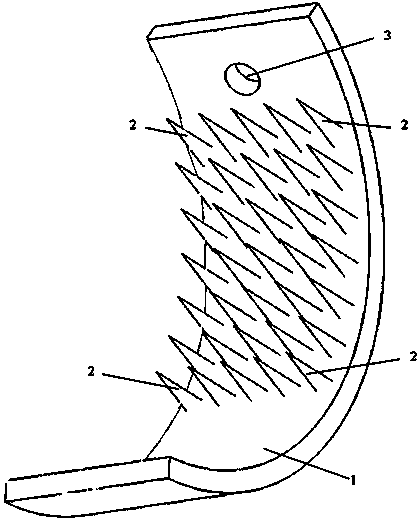
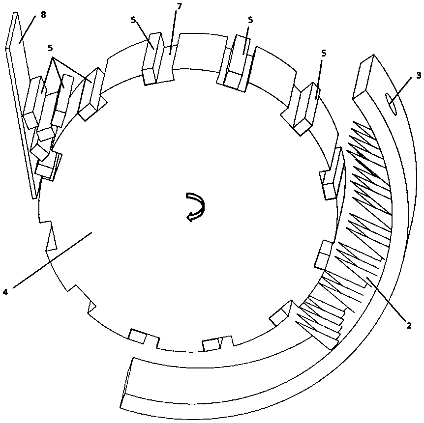
[0039] When the roller tile 1 is assembled with the roller 4, the distance from the tile body 6 to the central axis of the roller 4 decreases sequentially from top to bottom, and the turning device 2 is conical, and from top to bottom, the conical tip reaches the outer surface of the roller 4 The distance also decreases sequentially. Oil passage stays are 6mm wide and 5mm thick. The maximum distance from the conical tip to the outer surface of the roller 4 is 1 mm, and the minimum distance is 0 mm. The roller grooves 7 parallel to the central axis are uniformly distributed on the outer surface of the roller 4 . An inverted triangular area is formed between the feeding plate 8 and the roller 4, and the roller 4 rotates upwards through this inverted triangular area, and an oil channel stay 5 is installed in each roller groove 7. On the side where the roller 4 rotates downward, the oil passage stay 5 whose thick side is radially consistent with the roller 4 does not touch the c...

Embodiment 2

[0041] When the roller shoe 1 is assembled with the roller wheel 4, the distance from the tile body 6 to the center axis of the roller wheel 4 decreases sequentially from top to bottom, and the turning device 2 is barb-shaped, with the top point upward; The distance of the outer surface of the roller 4 also decreases successively. The oil passage stay is 5.7mm wide and 5.2mm thick. The maximum distance from the barbed top to the outer surface of the roller 4 is 0.5 mm, and the minimum distance is 0 mm. The roller grooves 7 parallel to the central axis are uniformly distributed on the outer surface of the roller 4 . An inverted triangular area is formed between the feeding plate 8 and the rollers 4, and the rollers rotate upwards through this inverted triangular area, and oil passage stays 5 are installed in each roller groove 7. On the side where the roller 4 rotates downward, the oil passage stay 5 whose thick side is radially consistent with the roller 4 does not touch the...

Embodiment 3

[0043] When the roller shoe 1 is assembled with the roller 4, the distance from the tile body 6 to the central axis of the roller 4 decreases sequentially from top to bottom, and the turning device 2 is hemispherical; from top to bottom, the hemispherical top reaches the outer surface of the roller 4 The distance also decreases sequentially. Oil channel stays are 6.2mm wide and 4.6mm thick. The maximum distance from the barbed top to the outer surface of the roller 4 is 1.3 mm, and the minimum distance is 0 mm. The roller grooves 7 parallel to the central axis are uniformly distributed on the outer surface of the roller 4 . An inverted triangular area is formed between the feeding plate 8 and the rollers 4, and the rollers rotate upwards through this inverted triangular area, and oil passage stays 5 are installed in each roller groove 7. On the side where the roller 4 rotates downward, the oil passage stay 5 whose thick side is radially consistent with the roller 4 does not ...


PUM


Abstract

The device discloses a device for aligning and splicing oil duct struts. The device comprises a feeding plate, a roller and a roller tile, wherein the roller can rotate along a center shaft, and roller grooves for placing the oil duct struts are formed in the outer side face of the roller at intervals; the roller tile comprises a tile body and an overturning device, the tile body is an arc-shapedplate, the overturning device for overturning the oil duct struts is arranged on the inner side of the tile body, and the bottom of the overturning device is fixed on the inner side of the tile body;the distance from the inner side surface of the tile body to the center shaft of the roller is gradually decreased from top to bottom, so that the distance from the top of the overturning device to the outer side face of the roller is also gradually decreased from top to bottom. According to the device for aligning the oil duct struts disclosed by the invention, the slotting, initial alignment, overturning and splicing of the oil duct struts can be completed. Oil duct struts without the need of overturning and with the need of post-overturning are kept at correct postures to reach dispensing paper, so that the splicing mechanization of the oil duct struts is realized.

Description

technical field [0001] The invention belongs to the technical field of power transformer manufacturing, and in particular relates to a device and method for aligning and bonding oil passage stays. Background technique [0002] The oil channel set in the transformer coil is to use the convection effect of the transformer oil to reduce the coil temperature, thereby improving the heat dissipation performance of the coil winding. The oil passage stay curtain is to evenly stick the oil passage stay with a rectangular cross section on the dispensing paper to prevent the oil passage from being blocked when the coil is pressed. The strip direction of the oil passage stay is called the length of the oil passage stay, the length of the rectangular cross section is called the width of the oil passage stay, and the width of the section is called the thickness of the oil passage stay. The industry standard stipulates that the surface bonded to the dispensing paper is one of the two surf...

Claims


Application Information

Patent Timeline
IPC IPC(8): H01F41/00H01F27/12
CPCH01F27/12H01F41/00
Inventor 张黎燕王云飞毛望军岳宗平张文斌赵伟伟郑浩杰
Owner HENAN MECHANICAL & ELECTRICAL VOCATIONAL COLLEGE
Why Eureka
Try Eureka