Eureka AIR delivers breakthrough ideas for toughest innovation challenges, trusted by R&D personnel around the world.

Fluid control apparatus

A technology of fluid control devices and flow controllers, which is applied in flow control, valve devices, flow monitors, etc., and can solve problems such as high cost and patient inconvenience

Inactive Publication Date: 2018-07-31
EPIC MEDICAL PTE LTD
View PDF6 Cites 1 Cited by
  • Summary
  • Abstract
  • Description
  • Claims
  • Application Information

AI Technical Summary

Problems solved by technology

[0003] Known PCA systems and devices require close monitoring by nursing staff to determine and control actual dose and flow, which is inconvenient and costly to the patient

Method used


Image

  • Fluid control apparatus
  • Fluid control apparatus
  • Fluid control apparatus

Examples


Embodiment Construction

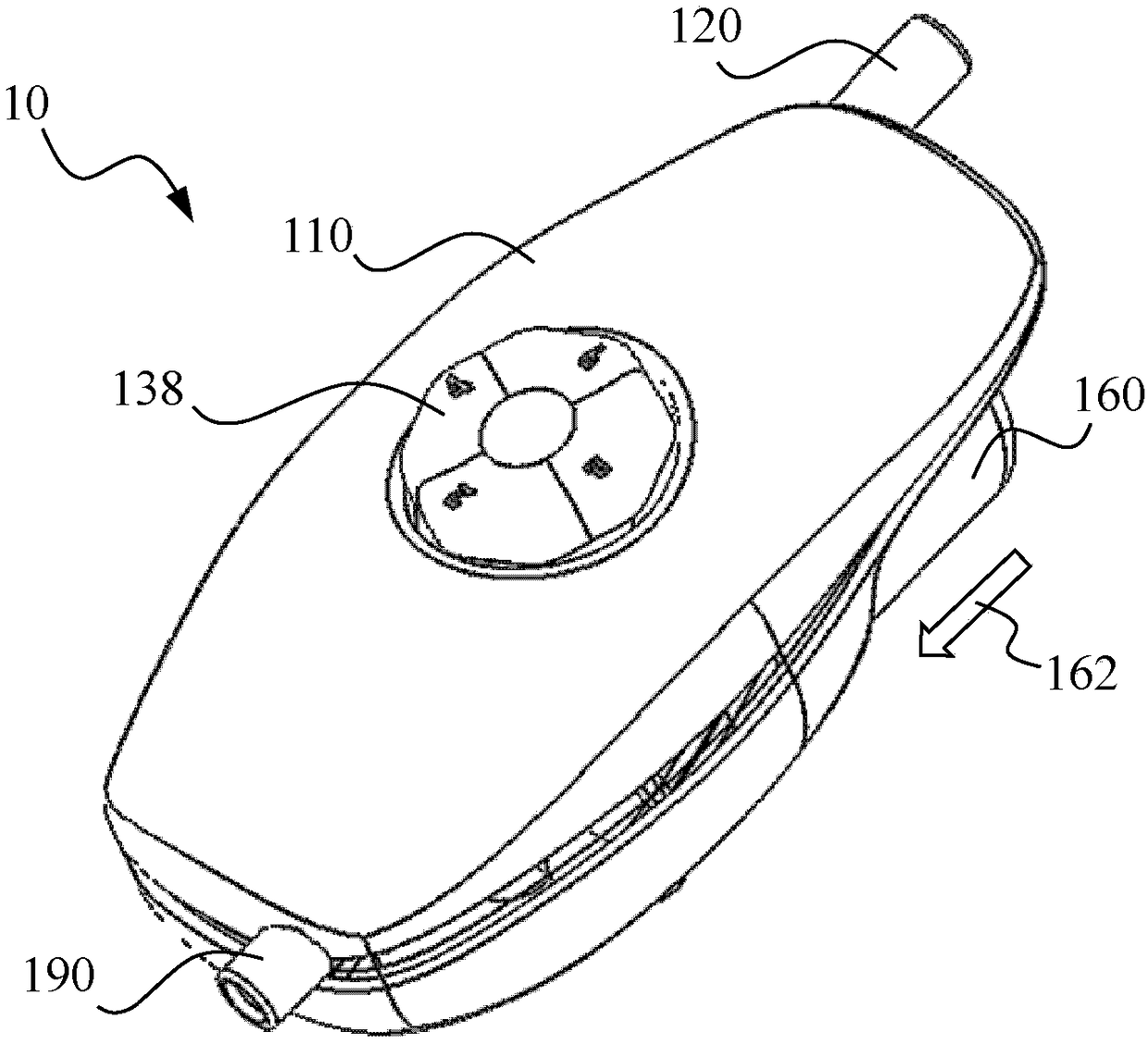
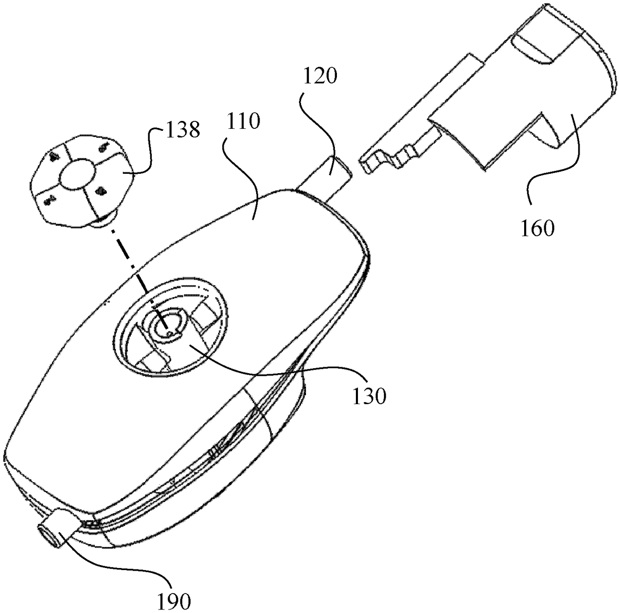
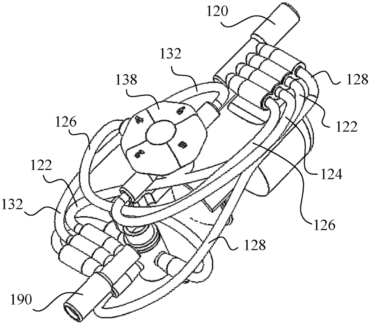
[0032] As shown in the drawings, according to an embodiment of the present invention, a flow control device 10 for a patient controlled anesthesia (PCA) infusion system includes a housing 110 and a fluid inlet 120 and a fluid outlet 190 coupled to the housing 110 . The inlet 120 and the outlet 190 may be integrally formed with the housing 110 or provided as separate components fixed to the housing 110 . A knob or dial 138 is coupled to the housing 110 and is rotatable relative to the housing 110 to control the flow selector 130 disposed in the housing 110 to vary the flow of fluid delivered from the inlet 120 to the outlet 190 by the device.

[0033] Inlet 120 is connected to fluid source 80 (eg, an infusion pump), and fluid outlet 190 is connected to patient 90 to be administered a fluid, such as an anesthetic drug. The device 10 includes a first flow channel 110a, wherein the front end 122a of the first selection conduit 122 is connected to the inlet 120, and the rear end 12...


PUM


Abstract

A fluid control apparatus comprises a housing; an inlet and an outlet coupled to the housing; a first flow path and a second flow path each having a front end connected to the inlet and a back end connected to the outlet to establish fluid communication between the inlet and the outlet through the first flow path and the second flow path; a flow controller coupled to the second flow path; and a reservoir in fluid communication with the second flow path via the flow controller. The flow controller is operable to fill the reservoir with the fluid from the inlet, and to supply fluid from the reservoir to the outlet to provide a dose of supplementary medication to a patient.

Description

technical field [0001] The present invention relates to a fluid control device. In particular, the present invention relates to a fluid control device for infusing liquid medicine into a patient. Background technique [0002] Patient-controlled anesthesia (PCA) is a technique and system preconfigured by caregivers based on the pain control requirements of individual patients. Compared with intramuscular injection, PCA has better pain relief effect, and it can supply the drug to the patient when needed. [0003] Known PCA systems and devices require close monitoring by the nursing staff to determine and control the actual dose and flow, which is inconvenient and costly to the patient. Contents of the invention [0004] In one embodiment, a fluid control device according to the present invention comprises a housing, an inlet and an outlet coupled to the housing; a first flow channel and a second flow channel, the first flow channel and the The second flow passages each ha...

Claims


Application Information

Patent Timeline
IPC IPC(8): A61M5/142A61M5/168
CPCA61M5/142A61M5/16804A61M5/16877A61M2005/1405A61M2205/3331A61M2202/048A61M5/16809A61M5/16813A61M2005/14208A61M5/14F16K11/0853
Inventor 李荣辉威卓云·翁迪
Owner EPIC MEDICAL PTE LTD
Why Eureka
Eureka Blog
Learn More