AI technical title is built by Patsnap AI team. It summarizes the technical point description of the patent document.
An image sensor and pixel technology, applied in the direction of image communication, image signal generator, color TV parts, etc., can solve the problems of sacrificing resolution, brightness response and signal-to-noise ratio, etc., to minimize motion artifacts, improve Quality, time spent reduction effect
Inactive Publication Date: 2018-07-31
CISTA SYST
View PDF4 Cites 11 Cited by
Summary
Abstract
Description
Claims
Application Information
AI Technical Summary
This helps you quickly interpret patents by identifying the three key elements:
Problems solved by technology
Method used
Benefits of technology
Problems solved by technology
While NIR detection is possible with NIR filters, it sacrifices performance in resolution, luminance response, and signal-to-noise ratio
Method used
Image
Click on the blue label to locate the original text in one second.
Reading with bidirectional positioning of images and text.
Examples
Embodiment 1
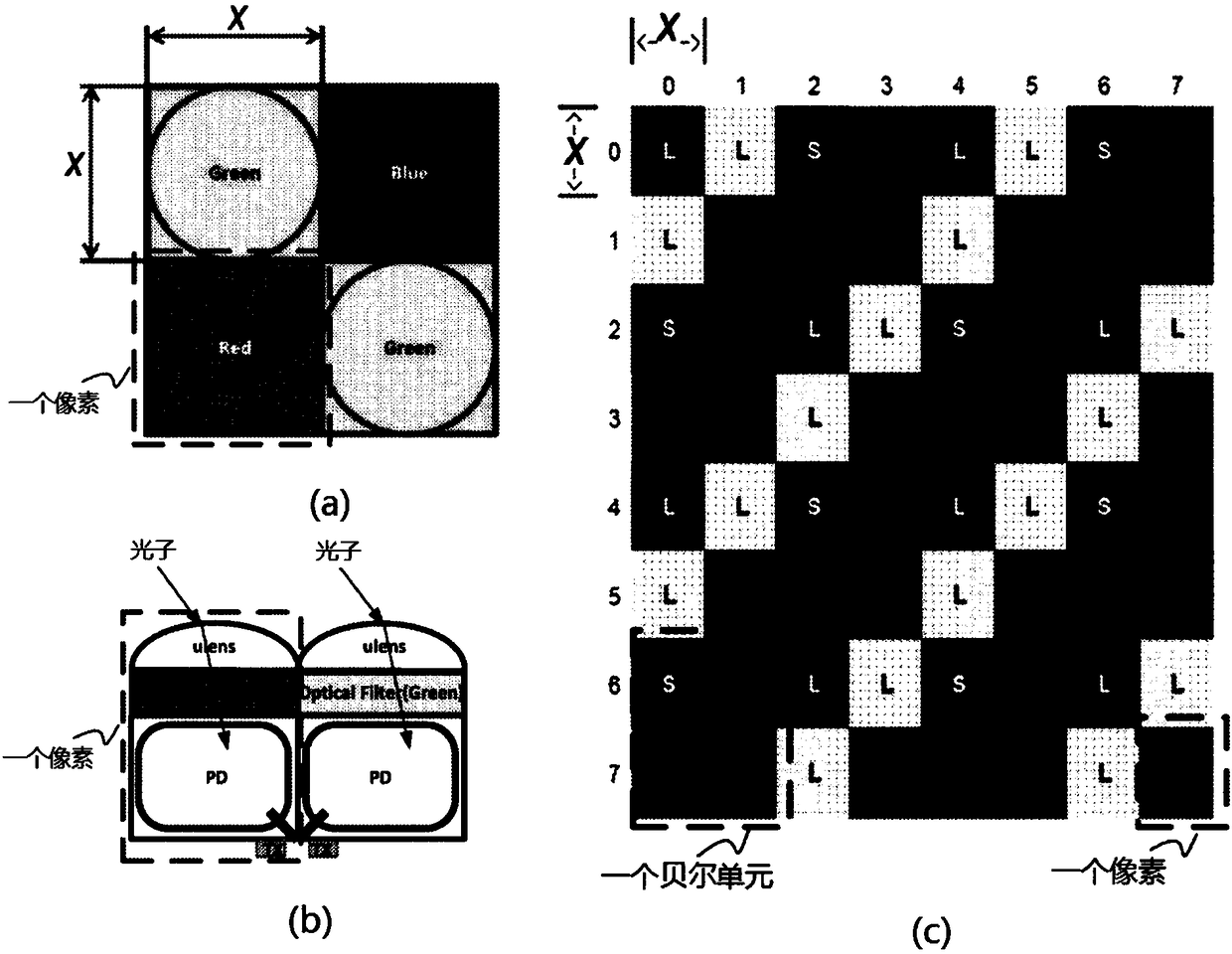
[0053] like figure 2 As shown, the present embodiment adopts an RGB quadrant pixel sensor structure, including: a Bell pattern cell array, wherein each Bell pattern cell includes four pixels, wherein each pixel further includes: a photodiode for detecting near-infrared light ( PD) and three photodiodes for detecting visible light, the four photodiodes are in a 2*2 configuration and have different integration times.
[0054] This embodiment includes: an array of optical filter combinations, where each optical filter combination corresponds to a pixel and its four photodiodes.
[0055] Each of the optical filters (Optical Filter) covers a photodiode, that is, a sub-pixel.
[0056] The pixels in the Bell pattern unit are arranged in 8 rows (0-7 marks) by 8 columns (0-7 marks), a total of 64, which are square, and each pixel is divided into 2*2 square sub-pixels, in the form of A checkerboard pattern in a 4*4 configuration, with a total of 256 sub-pixels.
[0057] The width of...
Embodiment 2
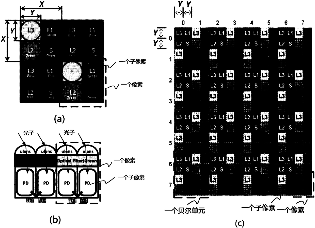
[0110] like Figure 11 As shown in (b) and (d), this embodiment adopts an RGB-NIR quadrant pixel sensor structure, including: an array of Bell pattern cells, wherein each Bell pattern cell contains 2*2 pixels, and each pixel further contains: One photodiode for near-infrared (NIR) detection and three photodiodes for visible light, with four photodiodes having different integration times.
[0111] Each pixel further includes three visible light filters and one NIR filter.
[0112] Each of said visible light filter and NIR filter covers a photodiode, ie a sub-pixel.
[0113] Each photodiode is further provided with a microlens for guiding incident light to reach the corresponding photodiode.
[0114] This embodiment includes an array of filter combinations, wherein each filter combination corresponds to a pixel and its four photodiodes, and the filter combination includes at least two different filters.
[0115] The filter combination array in one Bell mode unit includes: a r...
PUM
Abstract
The invention provides an image sensing device with a high dynamic range. The device includes an array of Bayer pattern units. Each of the Bayer pattern units comprises a plurality of pixels and eachof the plurality of pixels comprises a plurality of photodiodes. At least one of the plurality of photodiodes in each pixel is configured to detect near infrared (NIR) light and at least one of the plurality of photodiodes in each of the plurality of pixels is configured to detect visible light. At least two photodiodes have different integral times and each photodiode is provided with a micro lens which can guide incident light to the corresponding photodiode. The device also comprises an array of optical filter combinations. Each of the optical filter combinations may correspond to a pixel and the multiple photodiodes thereof and has at least two different filters, and at least two photodiodes corresponding to each optical filter are corresponding to different integral times. The devicecan integrate the times-domain HDR function with minimized motion artifact and multiple integral times and can be applied to visible light sensing, non-visible light sensing and the combination thereof to acquire HDR images with improved quality.
Description
technical field [0001] The invention relates to a technology in the field of visible light-infrared light image sensors, in particular to an image sensor device with a high dynamic range. Background technique [0002] Charge-coupled device (CCD) sensors and complementary metal-oxide-semiconductor (CMOS) sensors are widely used in visible light and infrared (IR) imaging, and dynamic range is an important performance index of these two solid-state sensing devices. Dynamic range can be defined as the ratio of the highest brightness to the lowest brightness an image sensor can detect. HDR (High Dynamic Range) images are usually clearer and richer than normal images because they better preserve both highlight and shadow details. Some existing techniques (such as exposurebracketing) generate an HDR image by taking multiple images with different exposure times and combining the features of each image. Such methods take tens of milliseconds and are susceptible to object motion, g...
Claims
Application Information
Patent Timeline
Application Date:The date an application was filed.
Publication Date:The date a patent or application was officially published.
First Publication Date:The earliest publication date of a patent with the same application number.
Issue Date:Publication date of the patent grant document.
PCT Entry Date:The Entry date of PCT National Phase.
Estimated Expiry Date:The statutory expiry date of a patent right according to the Patent Law, and it is the longest term of protection that the patent right can achieve without the termination of the patent right due to other reasons(Term extension factor has been taken into account ).
Invalid Date:Actual expiry date is based on effective date or publication date of legal transaction data of invalid patent.

