Improved air dust removing device

An air dust removal and improved technology, which is applied in the direction of coupling devices, two-part connecting devices, parts of connecting devices, etc., can solve problems such as air quality reduction, vacuum cleaner power failure, and wire tripping, so as to improve the safety of electricity use , the effect of avoiding electric shock accidents

Inactive Publication Date: 2018-08-03
广州正顺机械技术开发有限公司
View PDF2 Cites 0 Cited by
  • Summary
  • Abstract
  • Description
  • Claims
  • Application Information

AI Technical Summary

Problems solved by technology

[0002] In some public places such as bus stations, railway stations, etc., due to the large flow of people, a lot of dust will be generated. If these dusts are not disposed of in time, the air quality will be reduced, and therefore, it will affect people's health. As we all know, the traditional dust removal method is to use a vacuum cleaner to absorb the dust on the ground and corners. Traditional vacuum cleaners generally have long wires. After the plug is matched with the socket on the wall, the vacuum cleaner can be energized. In this way, the vacuuming operation can be carried out, but in public places, the wires are often kicked or tripped by passing pedestrians, which can make the plug and the socket loose, or even fall, so the vacuum cleaner can be cut off and can be used. It affects the dust removal efficiency, and in public places, the sockets are easily occupied by people, and electric shock accidents are also prone to occur

Method used


Image

  • Improved air dust removing device
  • Improved air dust removing device
  • Improved air dust removing device

Examples


Embodiment Construction

[0022] All features disclosed in this specification, or steps in all methods or processes disclosed, may be combined in any manner, except for mutually exclusive features and / or steps.

[0023] Any feature disclosed in this specification (including any appended claims, abstract and drawings), unless expressly stated otherwise, may be replaced by alternative features which are equivalent or serve a similar purpose. That is, unless expressly stated otherwise, each feature is one example only of a series of equivalent or similar features.

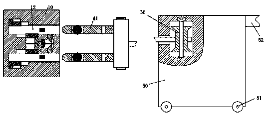
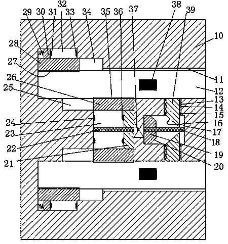
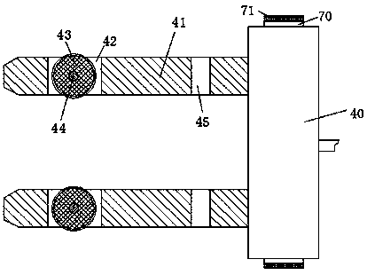
[0024] Such as Figure 1-5As shown, an improved air dust removal device of the device of the present invention includes a dust removal box body 50, a winding assembly arranged in the dust removal box body 50, a plug head 40, and a plug head 40 that matches and The socket 10 fixedly installed in the wall, the socket 10 is equipped with an insertion slot 12 with a notch facing the right, and the front and rear end walls of the insertion slot 12...


PUM


Abstract

The invention discloses an improved air dust removing device. The device comprises a dust removing box body, a winding assembly arranged in the dust removing box body, a plug and a socket which matches the plug and is fixedly arranged in a wall. Plug-in slots are symmetrically arranged up and down in the socket, wherein the openings of the plug-in slots face the right. Electric connecting pieces are arranged in front and rear end walls of each plug-in slot. A left sliding chamber and a right sliding chamber are arranged in the socket, and are between two plug-in sockets. A first motor is fixedly arranged between the left sliding chamber and the right sliding chamber. First sliding slots are symmetrically arranged up and down in the end wall, which is close to the left sliding chamber, of each plug-in slot, wherein the opening of each first sliding slot face the plug-in slot. The right half section of each first sliding slot is connected with the left sliding chamber. A left sliding plate capable of sliding left and right is arranged in the left sliding chamber. A left spiral rod which extends left and right is arranged in the left sliding plate in a matched manner.

Description

technical field [0001] The invention relates to the field of environmental dust removal, in particular to an improved air dust removal device. Background technique [0002] In some public places such as bus stations, railway stations, etc., due to the large flow of people, a lot of dust will be generated. If these dusts are not disposed of in time, the air quality will be reduced, and therefore, it will affect people's health. As we all know, the traditional dust removal method is to use a vacuum cleaner to absorb the dust on the ground and corners. Traditional vacuum cleaners generally have long wires. After the plug is matched with the socket on the wall, the vacuum cleaner can be energized. In this way, the vacuuming operation can be carried out, but in public places, the wires are often kicked or tripped by passing pedestrians, which can make the plug and the socket loose, or even fall, so the vacuum cleaner can be cut off and can be used. It affects the dust removal ...

Claims


Application Information

Patent Timeline
Patent Type & Authority Applications(China)
IPC IPC(8): H01R13/703H01R13/639H01R24/00
CPCH01R13/703H01R13/639H01R24/00
Inventor 邹承针陈建江
Owner 广州正顺机械技术开发有限公司
Why Eureka
Try Eureka