
Roller type straightening technological parameter setting method for optimizing head and tail part straightening

A technology of roller straightening and setting method, which is applied in electrical digital data processing, special data processing applications, instruments, etc., can solve the problems of complex roller structure, difficult to eliminate plate defects, and inability to guarantee straightening quality.

Active Publication Date: 2018-08-10
TAIYUAN UNIVERSITY OF SCIENCE AND TECHNOLOGY
View PDF6 Cites 5 Cited by
  • Summary
  • Abstract
  • Description
  • Claims
  • Application Information

AI Technical Summary

Problems solved by technology

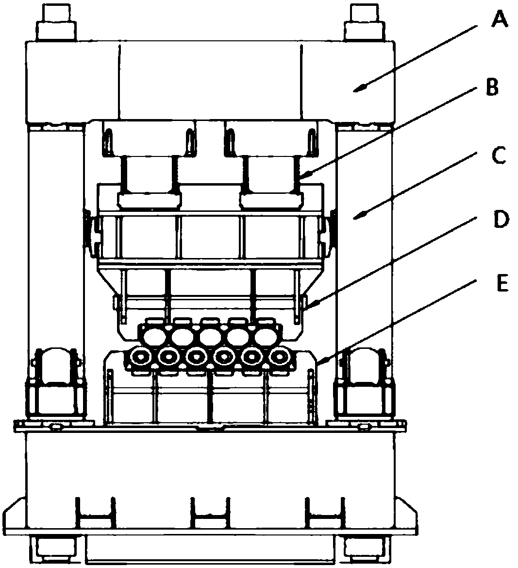
Straightening machine mechanical structure such as figure 1 As shown, the straightening roller is connected to the pressing device through the roller system box, and then acts on the frame and beam, and the structure of the roller system is complex
During the biting process when the head of the board enters the roller system, and the flicking process when the tail of the board leaves the straightening machine, the force changes, and the frame bounces to different degrees, resulting in the reduction during the bite and the tail flicking reduction. There is a large deviation in the setting process, resulting in a large number of plate shape defects in the head and tail of the plate during the straightening process
The difficulty of the straightening process is that the shape defects at the head and tail of the plate are difficult to eliminate, and the straightening quality cannot be guaranteed

Method used


Image

  • Roller type straightening technological parameter setting method for optimizing head and tail part straightening
  • Roller type straightening technological parameter setting method for optimizing head and tail part straightening
  • Roller type straightening technological parameter setting method for optimizing head and tail part straightening

Examples


Embodiment Construction

[0069] Now take a metal plate whose length, width, and thickness are 10 meters, 2 meters, and 0.3 meters respectively as an example to illustrate the implementation process. First, through the temperature sensor installed in front of the straightening machine, the temperature value of the plate to be straightened is measured to be 550°C. According to the temperature value, σ can be obtained S , and elastic modulus E see the table below

[0070]

[0071] 1. Construct the straightening process description space, determine the scope of the space, and the reduction S of the first roller in the upper row 2 , the value range is 0 to 5 times Reduction S of the last roller in the upper row N-1 The value range is 0 to 1.5 times Front roller position value B 1 Value range -25~+25mm and rear roller position value B N The value range is -25~+25mm. According to the reduction accuracy of the straightening machine, set the four process values ​​at intervals of 0.1mm, and then tra...


PUM


Abstract

The invention discloses a roller type straightening technological parameter setting method for optimizing head and tail part straightening and belongs to the field of plate straightening. The roller type straightening technological parameter setting method is characterized by comprising the following steps: 1, constructing a straightening technology description space including S2, S<N-1>, B1 and BN; 2, given S2, S<N-1>, B1 and BN, calculating the rolling reduction of each roller; 3, calculating the compensation dosage K of bouncing; 4, wherein the middle rolling reduction of a straightened plate is equal to the theoretical calculating value, according to an edge roller, correcting (refer to the Specification) to obtain a residual curvature; 5, during the plate biting process, an upper roller system Sj2=S2+K...Sj10=S10, obtaining the rolling reduction of each roller, and correcting S2' and S<N-1>' to obtain the residual curvature of the plate head position; 6, during the plate tail drifting process, S'j2=S2...S'j10=S10+K, obtaining the rolling reduction of each roller, correcting S2' and S<N-1>', and calculating the residual curvature of the plate tail; 7, comparing the residual curvatures of the plate head, plate middle part and the plate tail, and taking the largest residual curvature as the quality evaluation residual curvature CR after plate straightening under the setting value of the technology; and 8, calculating to obtain CR in each technology, comparing all CR to obtain the smallest value, enabling the smallest value to be equal to CF and taking CF as the optimal residual curvature of the plate under the setting of all straightening technologies.

Description

technical field [0001] The invention belongs to the technical field of plate straightening, and in particular relates to a method for setting parameters of a roller straightening process for optimizing head and tail straightening. Background technique [0002] At present, the roller straightening process of the plate is to repeatedly bend the plate through the longitudinally staggered roller system, so as to release the internal stress and improve the shape of the plate. Straightening machine mechanical structure such as figure 1 As shown, the straightening roller is connected to the pressing device through the roller system box, and then acts on the frame and beam, and the structure of the roller system is complex. During the biting process when the head of the board enters the roller system, and the flicking process when the tail of the board leaves the straightening machine, the force changes, and the frame bounces to different degrees, resulting in the reduction during ...

Claims


Application Information

Patent Timeline
Patent Type & Authority Applications(China)
IPC IPC(8): B21D1/02G06F17/50
CPCB21D1/02G06F30/17
Inventor 王效岗胡鹰郝建军程艳闫建云郝玺柴文婷
Owner TAIYUAN UNIVERSITY OF SCIENCE AND TECHNOLOGY
Learn More