Check patentability & draft patents in minutes with Patsnap Eureka AI!

Fuel injection devices for internal combustion engines

A technology of a fuel injection device and an internal combustion engine, which is applied in the directions of fuel injection control, internal combustion piston engine, combustion engine, etc., can solve the problems of insufficient fuel pressure for distribution and failure to diagnose faults.

Active Publication Date: 2021-04-09
MITSUBISHI MOTORS CORP
View PDF5 Cites 0 Cited by
  • Summary
  • Abstract
  • Description
  • Claims
  • Application Information

AI Technical Summary

Problems solved by technology

[0005] However, immediately after starting the internal combustion engine, for example, in an MT vehicle, if the shifting operation is wrong or the actual delivery fuel pressure is insufficient and the internal combustion engine stops, there is a problem that the fault diagnosis cannot be completed.

Method used


Image

  • Fuel injection devices for internal combustion engines
  • Fuel injection devices for internal combustion engines

Examples


Embodiment Construction

[0021] Hereinafter, embodiments of the present invention will be described with reference to the drawings.

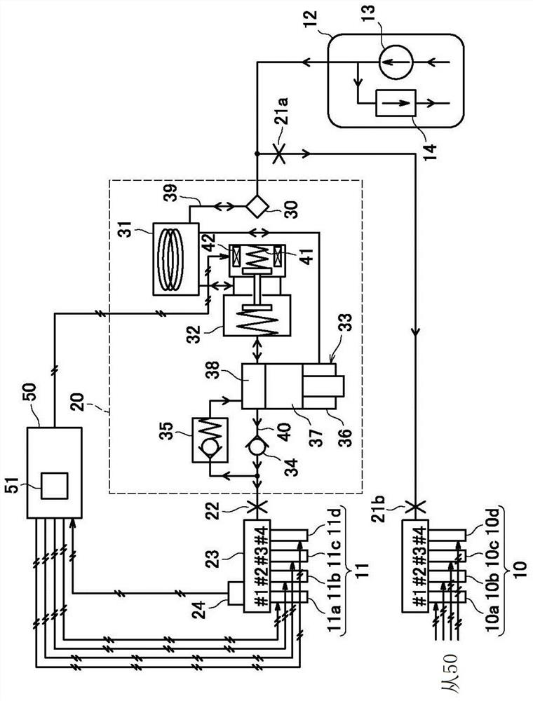
[0022] figure 1 It is a schematic configuration diagram of a fuel injection device for an internal combustion engine according to an embodiment of the present invention.

[0023] An engine (internal combustion engine) provided with a fuel injection device according to an embodiment of the present invention is, for example, a driving engine of an automobile, and is a four-cylinder gasoline engine. In the engine, each cylinder has an intake passage fuel injection valve 10 (10a-10d) that injects fuel into the intake passage and an in-cylinder fuel injection valve 11 (11a-11d) that injects fuel into the combustion chamber.

[0024] The injection port of the intake passage fuel injection valve 10 is arranged at the intake port of the internal combustion engine. Such as figure 1 As shown, the intake passage fuel injection valve 10 is supplied with fuel from a fuel tank 12 ...


PUM


Abstract

The present invention is a fuel injection device for an internal combustion engine. When the engine is started, the fuel pressure rise side control or the fuel pressure drop side control that changes the distribution fuel pressure is performed, and the fuel pressure sensor (24) is performed according to whether the detection value of the distribution fuel pressure has changed by a predetermined value or more until a predetermined time elapses. In the fuel injection device of the engine in the failure determination unit (51) of the failure determination, when the engine stops before a predetermined time elapses during the failure determination of the fuel pressure sensor (24), when the engine is at the When restarting after a stop, the failure judging unit (51) continues to operate from the elapsed time from the stop of the engine, and restarts the measurement of the predetermined time.

Description

technical field [0001] The present invention relates to a fault diagnosis technique of a high-pressure fuel supply device that supplies fuel to an in-cylinder fuel injection valve of an internal combustion engine. Background technique [0002] There is known an internal combustion engine provided with an in-cylinder fuel injection valve that injects fuel into a combustion chamber. The in-cylinder fuel injection valve can inject fuel into a high-pressure combustion chamber by supplying fuel pressurized by a high-pressure fuel supply device from a fuel tank. The high-pressure fuel supply device has, for example, a high-pressure fuel pump (piston pump) driven by an internal combustion engine and a flow control valve (relief valve). The fuel pressure (distribution fuel pressure) of the injection valve is detected, and the flow control valve is driven and controlled so that the distribution fuel pressure becomes the target fuel pressure. [0003] In addition, Japanese Patent No...

Claims


Application Information

Patent Timeline
Patent Type & Authority Patents(China)
IPC IPC(8): F02D41/22F02D41/06
CPCF02D41/061F02D41/062F02D41/22F02D2041/224Y02T10/40
Inventor 植松亨介古田贤宽松永英雄
Owner MITSUBISHI MOTORS CORP
Features
  • R&D
  • Intellectual Property
  • Life Sciences
  • Materials
  • Tech Scout
  • Unparalleled Data Quality
  • Higher Quality Content
  • 60% Fewer Hallucinations
Learn More