Pneumatic optical effect simulation device

A simulation device and aero-optics technology, applied in the field of aero-optics, can solve problems such as non-direct simulation, and achieve the effect of ensuring randomness, avoiding local periodic characteristics, and increasing the simulation range

Inactive Publication Date: 2018-08-10
HARBIN UNIV OF SCI & TECH
View PDF10 Cites 0 Cited by
  • Summary
  • Abstract
  • Description
  • Claims
  • Application Information

AI Technical Summary

Problems solved by technology

At present, many aero-optical effect simulators are optical simulators, such as the invention patent with application number 201410456264.8 "Aero-optical effect simulator based on distorted images", and algorithm simulation, such as the invention patent with application number 201310193486.0 "A Simulator Methods and systems for aero-optical effects", these simulation devices or methods do not directly generate the air flow that produces aero-optical effects, so they belong to indirect simulations, not direct simulations, so there is still a difference from the actual aero-optical effects

Method used


Image

  • Pneumatic optical effect simulation device
  • Pneumatic optical effect simulation device
  • Pneumatic optical effect simulation device

Examples


specific Embodiment 1

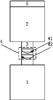
[0033] The structure schematic diagram of the aero-optical effect simulation device of this embodiment is as follows figure 1 shown. The aero-optical effect simulation device includes a blackbody 1 with an upward opening, and a tank body 2 with an opening above the blackbody 1 and a downward opening. The opening of the blackbody 1 and the opening of the tank body 2 are connected by a telescopic structure 3. A double-layer fan 4 is provided;

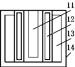
[0034] The black body 1 includes a ceramic layer 11, an intermediate layer 12, a cooling layer 13 and an outer shell 14 from the inside to the outside; the middle layer 12 is provided with a resistance wire, and the inner wall is provided with a temperature sensor, and the cooling layer 13 is filled with water. ; The schematic diagram of the structure of Heibody 1 is as follows: figure 2 shown;

[0035] The top of the tank body 2 is provided with an opening, and a cover 5 is provided on the opening;

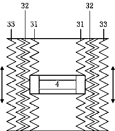
[0036] The telescopic structure ...

specific Embodiment 2

[0038] The vertical aero-optical effect simulation device of this embodiment is further defined on the basis of the specific embodiment one to include a water tank 6 and a water pump 7. The top and bottom of the cooling layer 13 each have an outlet, and the water pump 7 pumps the water tank 6 The water pumped into the outlet at the bottom of the cooling layer 13, and the water flows back to the water tank from the outlet at the top of the cooling layer 13, such as Figure 4 shown.

[0039] This structural design, utilizing the slow thermal conductivity of water, not only realizes the heat preservation of the ceramic layer 11 and the middle layer 12, ensures the stability of the aero-optical effect simulated by the aero-optical effect simulation device, but also realizes the cooling of the outer shell 14, Ensure experimental safety.

specific Embodiment 3

[0040] The vertical aero-optical effect simulation device of this embodiment, on the basis of the specific embodiment 1, further defines that the cover 5 is a furnace ring structure, including a plurality of annular rings with different diameters, nested in sequence, and with a stepped cross-section. Such as Figure 5 as shown, Figure 5 Shown is a schematic diagram of the superposition of three annular rings and the structure of the furnace ring after the superposition.

[0041] This structural design can adjust the opening size of the cover 5 by adjusting the number of annular rings, and then change the simulation effect of the aero-optical effect without changing other structures, parameters and technical indicators, thereby increasing the aero-optical effect of the present invention. The simulation range of the effect simulator.


PUM


Abstract

The invention discloses a pneumatic optical effect simulation device and belongs to the technical field of pneumatic optics. The pneumatic optical effect simulation device comprises a black body withan upward opening and a tank body arranged above the black body and provided with a downward opening, the opening of the black body is connected with the opening of the tank body through a retractablestructure, and the retractable structure is internally provided with a double-layer fan; the retractable structure sequentially comprises an inner-layer retractable pipe, a heat preservation layer and an outer-layer retractable pipe from inside to outside, the inner-layer retractable pipe is composed of a non-retractable end arranged in the middle and retractable pipes connected to the two ends of the non-retractable end, and an iris diaphragm structure is installed at the non-retractable end; the double-layer fan includes a first fan and a second fan which are arranged up and down and are different in blade number, rotation speed and rotation direction, and blades in the first fan and the second fan are different in width. According to the pneumatic optical effect simulation device, by utilizing the characteristic that cold gas and hot gas form strong convection, air flow with a pneumatic optical effect is directly generated, and therefore the purpose of directly simulating the pneumatic optical effect is achieved.

Description

[0001] This application is a divisional application of the invention patent application "An Aerodynamic Optical Effect Simulation Device". [0002] The original filing date: 2016-10-08. [0003] Original application number: 2016108763715. [0004] The name of the original invention: an aero-optical effect simulation device. technical field [0005] An aero-optical effect simulation device belongs to the technical field of aero-optics. Background technique [0006] When the aircraft flies in the atmosphere at high speed, due to the real gas effect between the optical hood and the free flow, the separation of the boundary layer induced by the shock wave, the mutual interference between the inviscid flow and the boundary layer, etc., resulting in changes in airflow density, temperature, etc. The complex flow field caused by changes in temperature, composition changes, and ionization of gas molecules will cause heat, thermal radiation, and image transmission interference to th...

Claims


Application Information

Patent Timeline
Patent Type & Authority Applications(China)
IPC IPC(8): G01M9/08G01M9/06G09B23/08
CPCG01M9/065G01M9/08G09B23/08G09B23/12
Inventor 于舒春刘爽孙剑明
Owner HARBIN UNIV OF SCI & TECH
Why Eureka
Try Eureka