Array air blowing type pneumatic optical effect simulation device

A technology of aero-optics and simulation device, which is applied in the field of aero-optics, can solve problems such as non-direct simulation, and achieve the effect of realizing random-state aero-optical effects.

Inactive Publication Date: 2017-03-15
HARBIN UNIV OF SCI & TECH
View PDF7 Cites 0 Cited by
  • Summary
  • Abstract
  • Description
  • Claims
  • Application Information

AI Technical Summary

Problems solved by technology

At present, many aero-optical effect simulators are optical simulators, such as the invention patent with application number 201410456264.8 "Aero-optical effect simulator based on distorted images", and algorithm simulation, such as the invention patent with application number 201310193486.0 "A Simulator Methods and systems for aero-optical effects", these simulation devices or methods do not directly generate the air flow that produces aero-optical effects, so they belong to indirect simulations, not direct simulations, so there is still a difference from the actual aero-optical effects

Method used


Image

  • Array air blowing type pneumatic optical effect simulation device
  • Array air blowing type pneumatic optical effect simulation device
  • Array air blowing type pneumatic optical effect simulation device

Examples


specific Embodiment 1

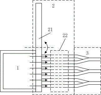
[0028] The structure diagram of the array air blowing aero-optical effect simulation device in this embodiment is as follows figure 1 shown (it should be noted that figure 1 In the airway coded cooling system 2, only one group of airways 22 is shown, and the airways 22 are reorganized, and the differences are replaced by dotted lines). The array air blowing aero-optical effect simulation device includes a blackbody 1, an airway coding cooling system 2 and an airway coding system 3;

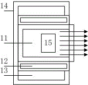
[0029] The black body 1 includes a ceramic layer 11, an intermediate layer 12, a cooling layer 13 and an outer shell 14 from the inside to the outside; the middle layer 12 is provided with a resistance wire, and the inner wall is provided with a temperature sensor, and the cooling layer 13 is filled with water. ; The inside of the black body 1 is provided with a fan 15, and the hot air is blown out from the opening of the black body 1, and the opening is an array structure of 1×n; the structural ...

specific Embodiment 2

[0034] The array blowing type aero-optical effect simulation device of this embodiment is further defined on the basis of the specific embodiment 1, and further includes a water tank 6 and a water pump 7, and the top and bottom of the cooling layer 13 have an outlet respectively, and the water pump 7 connects the water tank The water in 6 is pumped into the outlet at the bottom of the cooling layer 13, and the water flows back to the water tank from the outlet at the top of the cooling layer 13, as Figure 4 shown.

[0035] This structural design, utilizing the slow thermal conductivity of water, not only realizes the heat preservation of the ceramic layer 11 and the middle layer 12, ensures the stability of the aero-optical effect simulated by the aero-optical effect simulation device, but also realizes the cooling of the outer shell 14, Ensure experimental safety.

specific Embodiment 3

[0037] The above array air blowing aero-optical effect simulation device, on the basis of the first embodiment, further defines that it also includes an optical imaging system 8 arranged outside the airway coding system 3 and perpendicular to the airflow direction. The optical imaging system 8 is as follows: Figure 5 As shown, it includes a light source 81, a pinhole 82, a collimating lens 83, a grating 84, an objective lens 85 and an image sensor 86; the light beam emitted by the light source 81 passes through the pinhole 82 to form a point light source, and then collimates through the collimating lens 83 to form The parallel light beam illuminates the grating 84 , and the grating 84 and the image sensor 86 are respectively arranged on the object side and the image side of the objective lens 85 .

[0038] This structural design can monitor the aero-optical simulation effect, use the image obtained by the image sensor 86 to calculate the contrast attenuation of the grating 84,...


PUM


Abstract

The invention relates to an array air blowing type pneumatic optical effect simulation device and belongs to the pneumatic optical technology field. The array air blowing type pneumatic optical effect simulation device comprises a black body, an air channel coding cooling system and an air channel coding system, wherein an opening of a black body array structure is connected with one hole array of the air channel coding cooling system, after through an air channel,the opening is then connected with the air channel coding system, hot air of the black body array structure is outputted, and the outputted hot air and the external air form strong convection to generate the pneumatic optical effect; a rotation disc of the air channel coding cooling system rotates, n air channel access systems in different arrangement modes are realized, and coding is realized. The device is advantaged in that the characteristic that the cold and hot air together form strong convection is utilized, an air flow generating the pneumatic optical effect is directly generated, and a purpose of directly simulating the pneumatic optical effect is realized.

Description

technical field [0001] An array blowing type aero-optical effect simulation device belongs to the technical field of aero-optics. Background technique [0002] When the aircraft flies in the atmosphere at high speed, due to the real gas effect between the optical hood and the free flow, the separation of the boundary layer induced by the shock wave, the mutual interference between the inviscid flow and the boundary layer, etc., resulting in changes in airflow density, temperature, etc. The complex flow field caused by changes in temperature, composition changes, and ionization of gas molecules will cause heat, thermal radiation, and image transmission interference to the infrared imaging detection system, causing target deviation, shaking, and blurring. This effect is called the aero-optical effect. [0003] The aero-optical effect has a negative impact on the infrared imaging terminal guidance, which reduces the ability of the seeker to detect, track and identify the target...

Claims


Application Information

Patent Timeline
Patent Type & Authority Applications(China)
IPC IPC(8): G01M9/08G01M9/06G09B23/08
CPCG01M9/067G01M9/08G09B23/08G09B23/12
Inventor 赵烟桥于博洋
Owner HARBIN UNIV OF SCI & TECH
Why Eureka
Try Eureka