Hydraulic drive for machine tool chucks

A driving device and machine tool technology, applied in fluid pressure actuating devices, fluid pressure actuating system components, mechanical equipment, etc., can solve problems such as troublesome installation, large volume, and inconvenient actual operation

Active Publication Date: 2021-03-23
上海瑞麒美贸易有限公司 +1
View PDF6 Cites 0 Cited by
  • Summary
  • Abstract
  • Description
  • Claims
  • Application Information

AI Technical Summary

Problems solved by technology

However, as far as the commonly used hydraulic drive device is concerned, it has the problems of large volume, troublesome installation and complicated pipelines. Therefore, it is not convenient in actual operation and needs to be improved.

Method used


Image

  • Hydraulic drive for machine tool chucks
  • Hydraulic drive for machine tool chucks
  • Hydraulic drive for machine tool chucks

Examples


Embodiment Construction

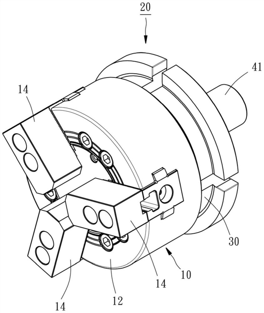
[0046] Please see first Figure 1 to Figure 3 , the collet 10 shown in the figure mainly includes a clamp seat 12 and three jaws 14, and the three jaws 14 are arranged on one end surface of the clamp seat 12 in a radial arrangement, and can be driven on the jaw drive shaft 16 Driven closer or farther away from each other, they are used to clamp or release the workpiece (not shown) to be processed. Since the chuck 10 is a known technology, in order to save space, the applicant will not repeat its detailed structure and operating principle here.

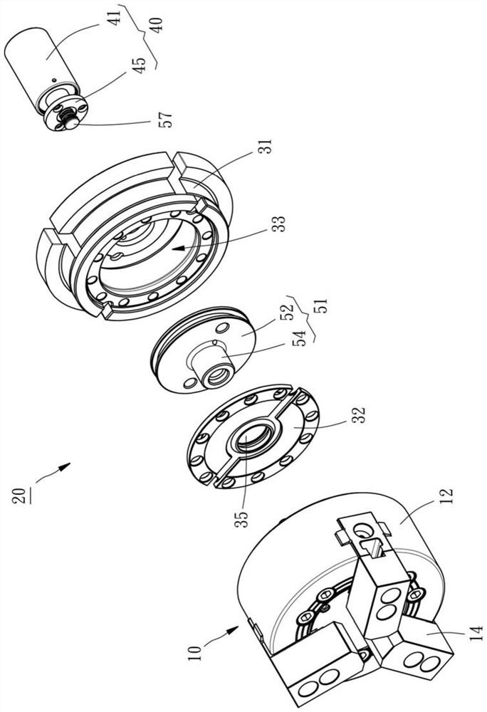
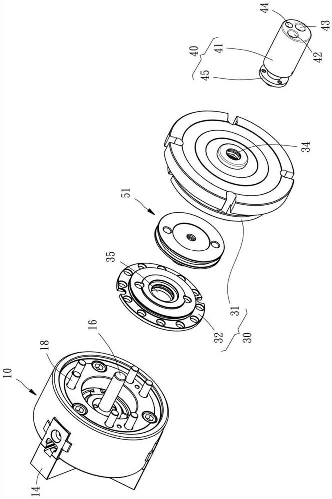
[0047] see again Figure 2 to Figure 4 , the hydraulic drive device 20 of the present invention includes a chuck connection seat 30 , an oil distribution valve 40 and a piston unit 50 .

[0048] The chuck connecting seat 30 is fixed on an end face of the clamping seat 12 facing away from each jaw 14 by a plurality of fixtures 18 (such as image 3 and Figure 4 shown). The chuck connection seat 30 has a seat body 31 and a cover pla...


PUM


Abstract

The invention provides an oil pressure driving device for a toolroom machine chuck. The oil pressure driving device comprises a chuck connecting seat, an oil distributing valve and a piston. Oil storage space and a shaft hole communicating with the oil storage space are formed in the chuck connecting seat. The oil distributing valve is provided with a valve body and an oil distributing shaft. Thevalve body communicates with compressed fluid outside, and the oil distributing shaft penetrates the shaft hole of the chuck connecting seat and guides the compressed fluid into the oil storage space.The piston is movably arranged in the oil storage space of the chuck connecting seat, and oil storage space is divided into a first chamber and a second chamber through the piston. Thus, when oil pressure is generated in the first chamber or the second chamber in a reciprocating manner, the piston or the chuck connecting seat can generate relative displacement, and then the toolroom machine chuckis driven by the piston or the chuck connecting seat.

Description

technical field [0001] The invention relates to a machine tool, in particular to an oil pressure driving device for a chuck of a machine tool. Background technique [0002] The so-called hydraulic chuck mainly drives multiple jaws to reciprocate along the chute through the hydraulic drive device, so that these jaws jointly clamp the workpiece to be processed. However, as far as the commonly used hydraulic drive device is concerned, there are only problems of large volume, troublesome installation and complicated pipelines. Therefore, it is inconvenient in actual operation and needs to be improved. Contents of the invention [0003] The main object of the present invention is to provide a hydraulic drive device for a chuck of a machine tool, which has a simple structure, is easy to operate, and can effectively reduce the volume. [0004] In order to achieve the above purpose, the hydraulic drive device for the machine tool chuck provided by the present invention includes a...

Claims


Application Information

Patent Timeline
Patent Type & Authority Patents(China)
IPC IPC(8): F15B13/02F15B15/14F15B15/20F15B21/00
CPCF15B13/021F15B13/022F15B15/1423F15B15/1476F15B15/20F15B21/001
Inventor 吴亚爵
Owner 上海瑞麒美贸易有限公司
Why Eureka
Try Eureka