
Module with printed circuit board

A printed circuit board and conductive connection technology, applied in the field of modular products, can solve problems such as unfavorable assembly experience for consumers, unfavorable product internal structure storage function, and unfavorable production line workers mass production, etc., to improve convenience. , optimize the wire layout, improve the effect of safety and reliability

Active Publication Date: 2018-08-24
HUNAN YUEGANG MOOKRAY IND CO LTD
View PDF4 Cites 0 Cited by
  • Summary
  • Abstract
  • Description
  • Claims
  • Application Information

AI Technical Summary

Problems solved by technology

This wiring method is not conducive to the storage function of the product's internal structure, nor is it conducive to the mass production of production line workers, nor is it conducive to consumers' independent creative assembly experience

Method used


Image

  • Module with printed circuit board
  • Module with printed circuit board
  • Module with printed circuit board

Examples


Embodiment 1

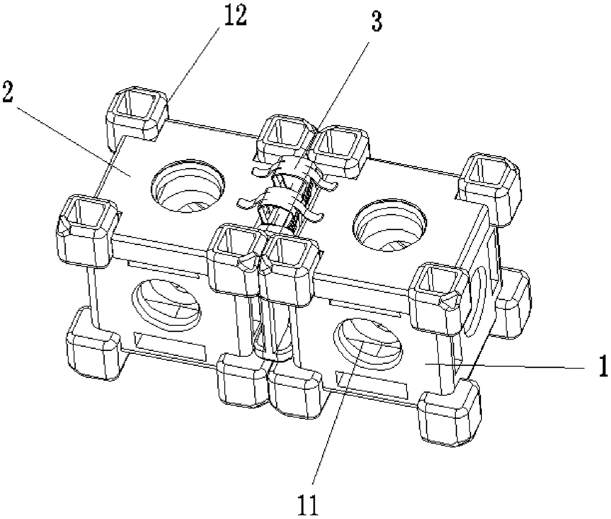
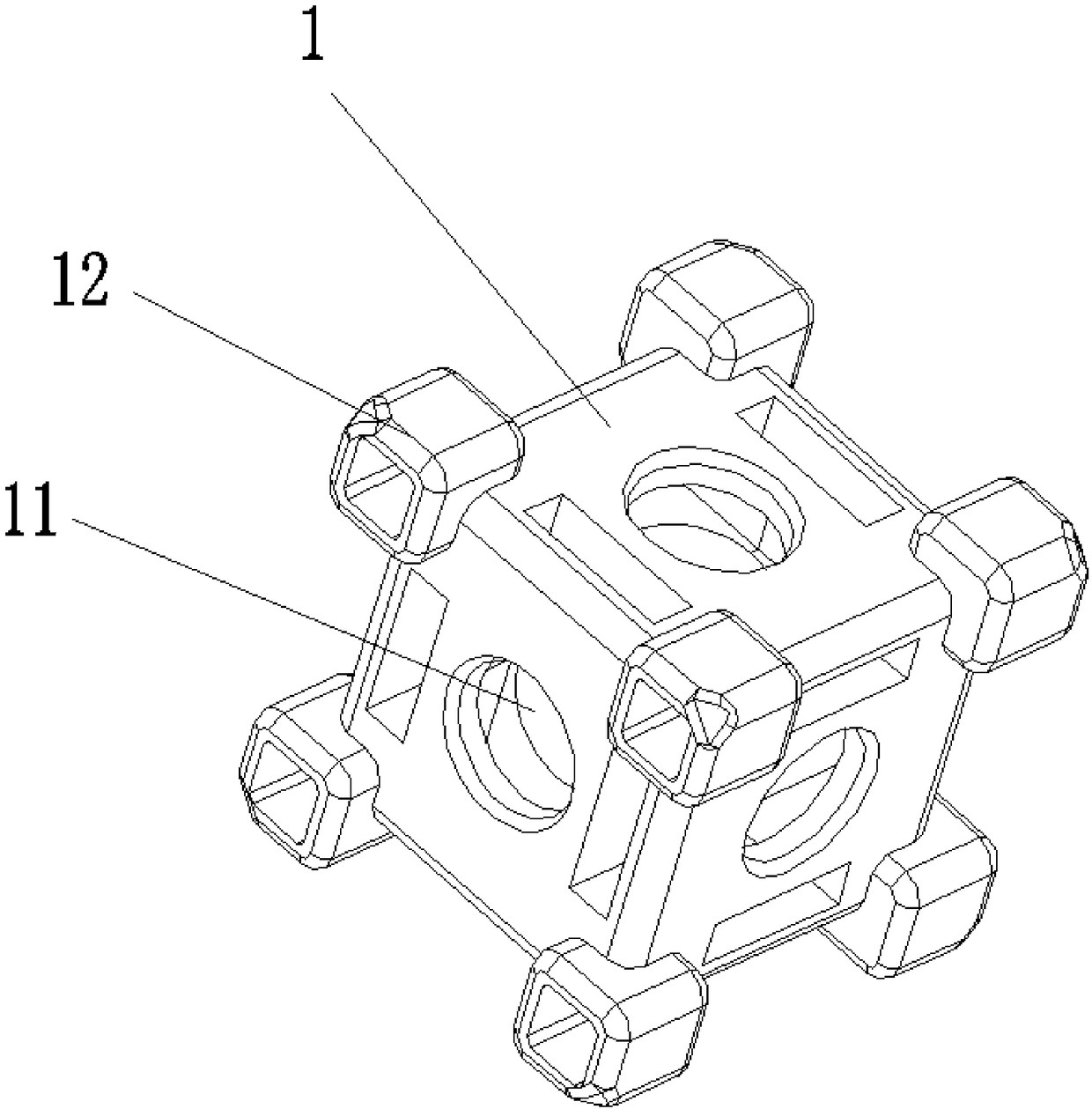
[0039] like Figure 1-Figure 10 As shown, the embodiment of the present invention provides a module with a printed circuit board, including a module body 1, a printed circuit board 2 and a conductive connector 3;

[0040] The module body 1 has a regular hexahedral structure, and the middle part of each surface is provided with a first through hole 11; each corner is provided with a regular hexahedral protrusion 12, and the regular hexahedral protrusion 12 and the side surface of the module body 11 form a ten-dimensional structure. glyph inner groove;

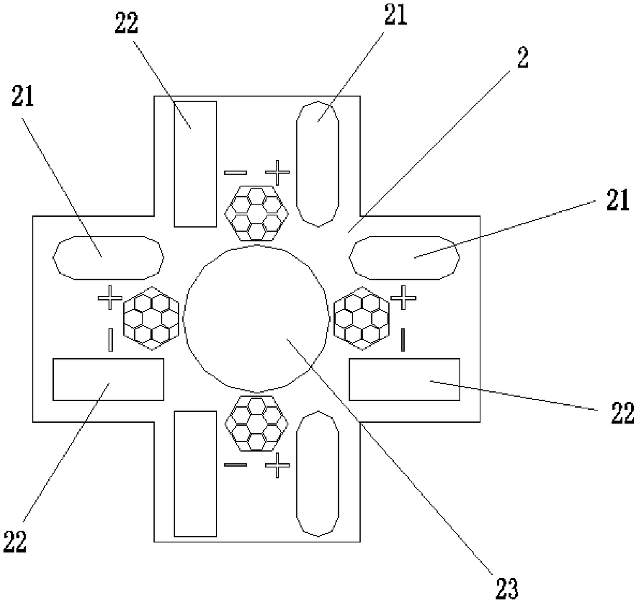
[0041] The printed circuit board 2 is a circuit board whose structure matches the cross-shaped inner groove, and the printed circuit board 2 is provided with a positive electrode connection terminal 21 and a negative electrode at the end positions along the four directions of the cross-shaped inner groove. Connecting end 22; all positive connecting ends 21 are electrically connected to each other, and all negative connecting en...

Embodiment 2

[0051] like figure 2 , Figure 10-Figure 16 As shown, the difference between the embodiment of the present invention and embodiment 1 is that the embodiment of the present invention includes not only the module body 1 and the printed circuit board 2, but also includes a decorative sheet 5 and a puncture elastic sheet 6; wherein, the decorative sheet 5 The back side is provided with buckle and piercing shrapnel mount 51, and the bottom of piercing shrapnel 6 snaps into the piercing shrapnel mount 51; the second through hole 23 in the middle of the printed circuit board 2 can pass through the decorative plate In the installed state, the printed circuit board 2 is arranged between the decorative sheet 5 and the module body 1, the positive ports 21 of adjacent printed circuit boards 2 overlap each other, and the negative ports 22 overlap each other The decorative sheet 5 is clamped on the module body 1, and the piercing elastic sheet 6 pierces the overlapped positive port 21 or ...


PUM


Abstract

The invention discloses a module with a printed circuit board, which comprises a module body, a printed circuit board and a conductive connector, wherein the module body has a regular hexahedral structure; the middle part of each face is provided with a first through hole; each corner is provided with a regular hexahedral bulge, and the regular hexahedral bulge and the side surface of the module body form a cross inner groove; the printed circuit board is a circuit board matched with the cross inner groove in structure, and the end part positions, along the four directions of the cross inner groove, on the printed circuit board are provided with positive and negative connection terminals; and in a mounting state, the printed circuit board is buckled outside the cross inner groove, and theadjacent two printed circuit boards are connected through the conductive connector. According to the module with the printed circuit board disclosed in the invention, a wiring circuit of a modular product is changed to a form of the printed circuit board plus the conductive connector, the technical problem of difficult wiring of the modular product can be effectively solved, and the wire layout ofthe modular product is optimized.

Description

technical field [0001] The invention belongs to the technical field of modular products, and in particular relates to a module with a printed circuit board. Background technique [0002] Modular lighting products are assembled from several functional modules according to the product shape, and have the characteristics of high flexibility, strong functionality, and excellent structure. Widely used in commercial lighting, home lighting, decorative lighting, etc. Favored and loved by consumers. [0003] The wiring situation of the modularized lighting products in the prior art is that the wires are either placed in the through holes and wiring grooves of the functional modules, or the wires are placed on the inner surface of the decorative sheet. This wiring method is not conducive to the storage function of the internal structure of the product, is not conducive to the mass production of production line workers, and is not conducive to the independent creative assembly exper...

Claims


Application Information

Patent Timeline
Patent Type & Authority Applications(China)
IPC IPC(8): H05K1/18
Inventor 朱衡
Owner HUNAN YUEGANG MOOKRAY IND CO LTD
Learn More