Electric wire deicing device

A wire and battery technology, applied in the installation of cables, electrical components, overhead installation, etc., can solve the problems of system safety impact, high cost, and threat to the safe and stable operation of the power grid

Active Publication Date: 2018-09-04
海门卡汶纺织品有限公司
View PDF5 Cites 2 Cited by
  • Summary
  • Abstract
  • Description
  • Claims
  • Application Information

AI Technical Summary

Problems solved by technology

[0002] In most parts of our country, there is a large amount of snowfall every year, resulting in the formation of ice on the transmission lines of a large number of high-voltage transmission lines. These ice coatings have caused serious harm to the cables and towers of high-voltage transmission lines, especially in recent years. The icing of high-voltage transmission lines caused cable breakage and tower collapse, resulting in large-scale power outages, seriously threatening the safe and stable operation of the power grid, and causing great losses to my country's economic construction and people's lives.
At present, most of the deicing work on transmission lines in China still adopts manual deicing methods, and the deicing method is manually struck with sticks, which requires more personnel and resource input and cannot achieve the required efficiency. It is also very difficult Protect the life safety of deicing personnel
Or use the high-voltage line to melt ice, but high-voltage line ice-melting consumes too much energy, and the energy consumption of mechanical de-icing is much less than that of high-current ice-melting
The high-current ice-melting method is more efficient, but it is costly and complicated to operate, which has a great impact on system safety

Method used


Image

  • Electric wire deicing device
  • Electric wire deicing device
  • Electric wire deicing device

Examples


specific Embodiment approach

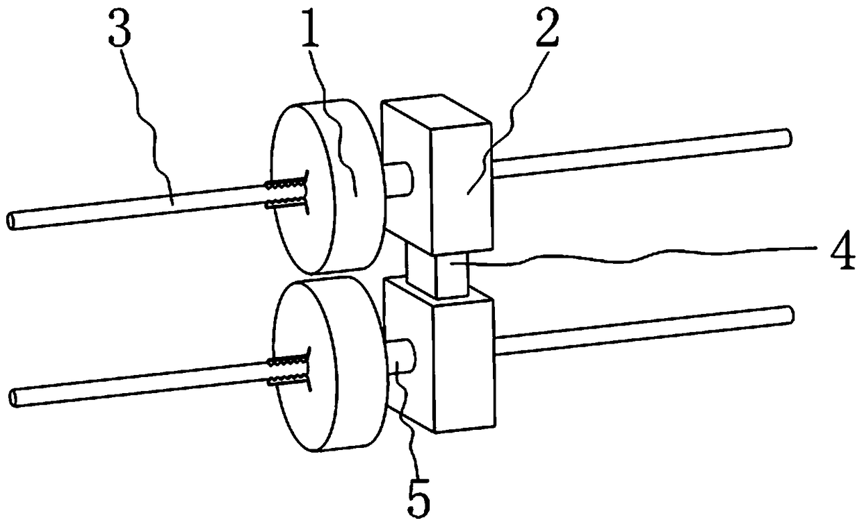
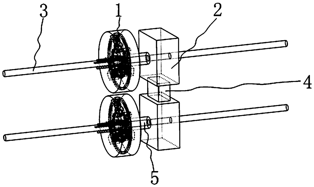
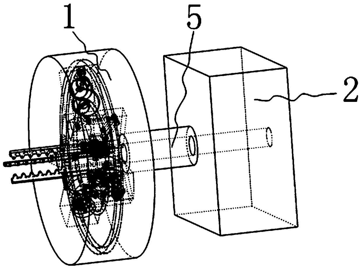
[0061] The specific embodiment: when using the electric wire 3 deicing device designed by the present invention, the electric wire 3 deicing device is placed on two adjacent electric wires 3 up and down; two running gears 2 are controlled so that the two running gears 2 are Drive the two deicing mechanisms 1 to move forward through the corresponding rotating shaft sleeve 5, and at the same time make the two deicing mechanisms 1 rotate around the corresponding electric wires 3; at the same time control the work of the driving motor 18 in the deicing mechanism 1 to drive The motor 18 will drive the corresponding second gear 20 to rotate; the second gear 20 will drive the corresponding first gear 19 to rotate; the rotation of the first gear 19 will drive the corresponding flexible shaft 21 to rotate; under normal conditions, the rotation of the flexible shaft 21 will drive the corresponding The first adjustment shaft 53, the second adjustment shaft 67 and the third adjustment shaf...


PUM


Abstract

The invention, which belongs to the technical field of electric wire deicing, particularly relates to an electric wire deicing device comprising deicing mechanisms, running mechanisms, a connecting plate and a rotating shaft sleeve. With the design of fifth oscillating bars, the impact forces are applied on the ice on a wire by oscillation of the fifth oscillating bars and the ice is broken by theimpact forces, so that the ice cleaning effect is realized. Meanwhile, the corresponding deicing mechanisms are driven to make rotation by the running mechanisms to drive corresponding three fifth oscillating bars to rotate; and the deicing effect is enhanced by oscillation of the fifth oscillating bars. The ice on the wire becomes solid and thus the deicing difficulty is increased in cold weather. Besides, each fifth oscillating bar in the two deicing mechanisms has different speeds by adjusting and changing the oscillation speeds of all fifth oscillating bars and thus the stress situation of the ice on the wire is changed, so that different impact forces are applied on the ice at the same part of the wire in a circumferential direction and thus the deicing effect is improved.

Description

Technical field [0001] The invention belongs to the technical field of wire deicing, and in particular relates to a wire deicing device. Background technique [0002] In most parts of our country, there is a large amount of snowfall every year, resulting in the formation of ice on the transmission lines of a large number of high-voltage transmission lines. These ice coatings have caused serious harm to the cables and towers of high-voltage transmission lines, especially in recent years. The icing of high-voltage transmission lines caused cable breakage and tower collapse, resulting in large-scale power outages, seriously threatening the safe and stable operation of the power grid, and causing great losses to my country's economic construction and people's lives. At present, most of the deicing work on transmission lines in China still adopts manual deicing methods, and the deicing method is manually struck with sticks, which requires more personnel and resource input and cann...

Claims


Application Information

Patent Timeline
IPC IPC(8): H02G7/16
CPCH02G7/16
Inventor 朱怀新
Owner 海门卡汶纺织品有限公司
Why Eureka
Try Eureka