Bolting Device

A connecting device and bolt technology, applied in the direction of rod connection, connecting components, cranes, etc., can solve the problem of increasing the force of moving bolts

Active Publication Date: 2018-09-07
MANITOWOC CRANE GROUP FRANCE
View PDF8 Cites 0 Cited by
  • Summary
  • Abstract
  • Description
  • Claims
  • Application Information

AI Technical Summary

Problems solved by technology

It is also impossible to completely rule out the possibility that the bolts are "twisted" relative to each other to a certain extent, which additionally increases the force required to move the bolts

Method used


Image

  • Bolting Device
  • Bolting Device
  • Bolting Device

Examples


Embodiment Construction

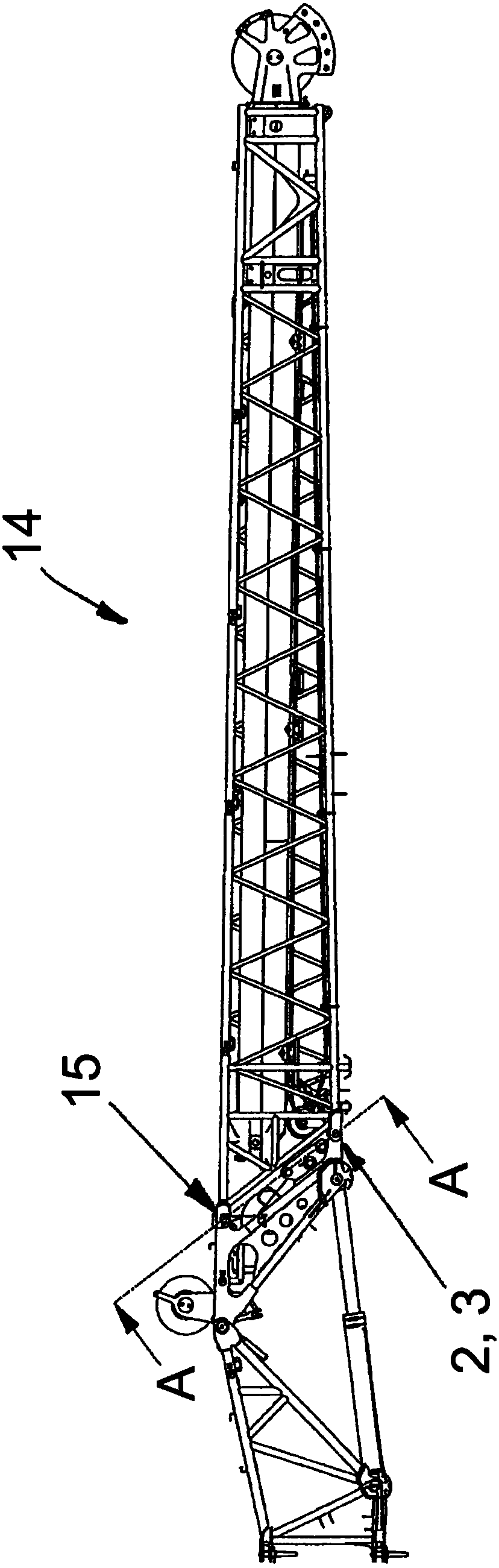
[0028] In order, for example, to be able to operate the telescopic boom of a mobile crane beyond the upper edge of a building, a jib head is often used. Such boom heads are for example made of figure 1 The reference numeral 14 in represents. figure 1 The jib head shown in includes a lattice masthead structure in which its proximal end ( figure 1 ) can be bolted horizontally to a head adapter (not shown in detail), which in turn can be bolted to a telescoping boom of a mobile crane (not shown). The pitch angle of the boom head 14 can be changed relative to the telescoping boom by the hydraulic cylinders of the head adapter.

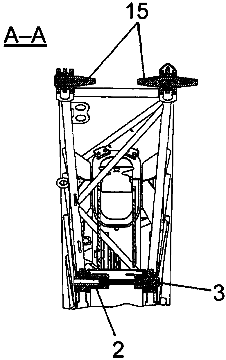
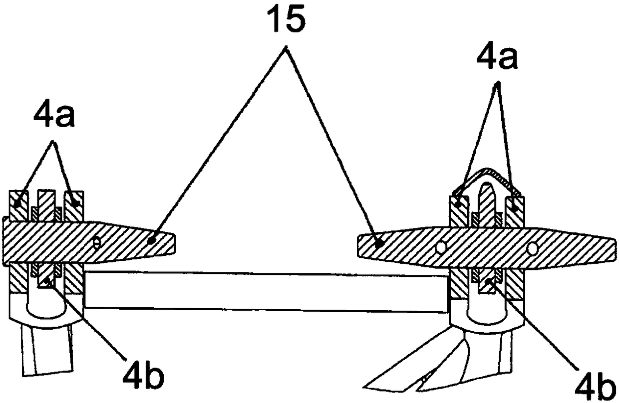
[0029]In order to bolt the lattice masthead to the head adapter and thus to the telescoping jib, the optionally fitted lattice masthead 14 comprises two opposing bolts 2 and 3 according to the invention. bolt connection device. In the example shown, the bolting location above this between the truss mast and the head adapter is bolted by common bolts 15...


PUM


Abstract

The invention relates to a bolting device having two bolts which are held rotationally secure and coupled to each other via a spindle element, wherein: a first bolt is connected via a threaded engagement to a corresponding thread of the spindle element; rotating the spindle element about its central longitudinal axis causes the first bolt to move along the longitudinal axis; and a second bolt is rotationally mounted on the spindle element in a fixed axial position. The invention also relates to a crane jib head comprising such a bolting device, for bolting a lattice masthead to a head adaptor.

Description

technical field [0001] The invention relates to a screw connection device for screwing crane components to one another. The invention also relates to a crane jib head comprising such a bolt connection. Background technique [0002] When erecting a crane, the individual crane components are usually bolted to each other. A very widely used solution is to drive substantially cylindrical bolts into special sockets in the parts to be connected, and / or to drive them out after use. However, this very simple solution requires that the corresponding bolt sockets are easily accessible by tapping, which is not always possible in more complex and compact designs. In order to be able to carry out screw connections in difficult-to-reach locations or in confined spaces, screw connection systems in which the screws are pressed in hydraulically, pneumatically or mechanically or removed again from their sockets have proven to be valuable. [0003] Thus, for example, US8522988B2, US2004 / 010...

Claims


Application Information

Patent Timeline
Patent Type & Authority Applications(China)
IPC IPC(8): B66C23/62B66C23/68
CPCB66C23/62B66C23/68B66C23/64B66C23/702B66C23/70F16B7/18
Inventor N·艾任特罗特A·海格
Owner MANITOWOC CRANE GROUP FRANCE
Why Eureka
Try Eureka