Improved electric power device

An improved technology for power devices, which is applied to coupling devices, components of connecting devices, circuits, etc., can solve problems such as potential safety hazards of power sockets, influence of power-consuming equipment, and disconnection of power connectors, so as to improve the safety of power consumption Sex, the effect of avoiding electric shock accidents

Inactive Publication Date: 2018-09-07
佛山拓达科技有限公司
View PDF4 Cites 0 Cited by
  • Summary
  • Abstract
  • Description
  • Claims
  • Application Information

AI Technical Summary

Problems solved by technology

[0002] In the power system, the power connection base and the power connection head are the power accessories that people use frequently. It is connected to the outside, and the power supply piece extends into the power connection slot, and the power supply piece is directly connected to the mains. Therefore, when an ordinary metal rod is inserted into the power connection slot, it will contact the power supply piece, which will cause an electric shock accident. Therefore, there is a great potential safety hazard in the traditional power socket, and when the traditional power socket is matched with the power socket, if you accidentally kick the power socket or kick the power cord, it will cause the power socket to fall off , which will cause a sudden power failure of the electrical equipment, which will easily affect the electrical equipment

Method used


Image

  • Improved electric power device
  • Improved electric power device
  • Improved electric power device

Examples


Embodiment Construction

[0022] All features disclosed in this specification, or steps in all methods or processes disclosed, may be combined in any manner, except for mutually exclusive features and / or steps.

[0023] Any feature disclosed in this specification (including any appended claims, abstract and drawings), unless expressly stated otherwise, may be replaced by alternative features which are equivalent or serve a similar purpose. That is, unless expressly stated otherwise, each feature is one example only of a series of equivalent or similar features.

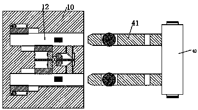
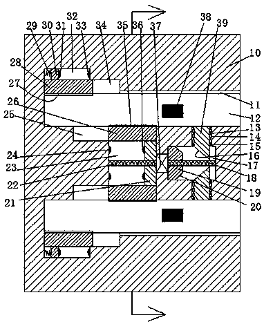
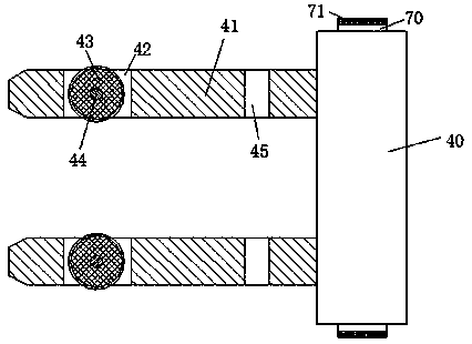
[0024] like Figure 1-5As shown, an improved power device of the device of the present invention includes a power socket 10 fixedly installed in the wall and a power socket 30 connected to the equipment, and the power socket 10 is symmetrically arranged with an opening facing right The insertion slot 12, the front and rear end walls of the insertion slot 12 are provided with a power supply piece 38, and the power connection base 10 is provide...


PUM


Abstract

The invention discloses an improved electric power device. The improved electric power device comprises a power connection seat fixedly mounted in a wall and a power connection head connected with equipment; plugging slots with rightwards-facing openings are formed in the power connection seat, wherein the plugging slots are in longitudinal symmetry; power supply sheets are arranged at the front end walls and rear end walls of the plugging slots; a left sliding cavity and a right sliding cavity located between the two plugging slots are formed in the power connection seat; a driving motor is fixedly mounted between the left sliding cavity and the right sliding cavity; first sliding slots of which the openings face the plugging slots are formed in end walls of the plugging slots, wherein the first sliding slots are in longitudinal symmetry, and the end walls of the plugging slots are adjacent to the left sliding cavity; the right half segments of the first sliding slots are communicatedwith the left sliding cavity; a left sliding plate which can slide leftwards and rightwards is mounted in the left sliding cavity; a left threaded rod which extends leftwards and rightwards is mounted in the left sliding plate in a screw-thread fit manner; the left end of the left threaded rod is rotationally mounted in the left end wall of the left sliding cavity; and the right end of the left threaded rod is in power connection with the driving motor.

Description

technical field [0001] The invention relates to the field of power connection of electric equipment, in particular to an improved electric device. Background technique [0002] In the power system, the power connection base and the power connection head are the power accessories that people use frequently. It is connected to the outside, and the power supply piece extends into the power connection slot, and the power supply piece is directly connected to the mains. Therefore, when an ordinary metal rod is inserted into the power connection slot, it will contact the power supply piece, which will cause an electric shock accident. Therefore, there is a great potential safety hazard in the traditional power socket, and when the traditional power socket is matched with the power socket, if you accidentally kick the power socket or kick the power cord, it will cause the power socket to fall off , which will cause a sudden power failure of the electrical equipment, which will e...

Claims


Application Information

Patent Timeline
IPC IPC(8): H01R13/627H01R13/703
CPCH01R13/6278H01R13/7036
Inventor 潘桂兰詹胜超
Owner 佛山拓达科技有限公司
Why Eureka
Try Eureka