A non-metallic compensator for power plant boiler flue gas transmission pipeline

A non-metallic compensator and boiler flue gas technology, which is applied to expansion compensation devices for pipelines, pipe components, exhaust gas devices, etc. Achieve the effect of novel structure setting, prolong service life and long service life

Inactive Publication Date: 2020-10-16
永康市简零贸易有限公司
View PDF7 Cites 0 Cited by
  • Summary
  • Abstract
  • Description
  • Claims
  • Application Information

AI Technical Summary

Problems solved by technology

[0005] The flue gas delivery pipeline in the prior art has the following problems during transportation: 1. Due to the large amount of organic waste gas such as carbon dioxide and sulfur dioxide in the flue gas, when the flue gas is transported, the delivery pipeline will be eroded to a certain extent
2. Due to the high temperature of the boiler flue gas, it will cause thermal expansion and contraction of the transportation pipeline during transportation, resulting in deformation of the transportation pipeline. In severe cases, it will also cause leakage of the transportation pipeline
[0007] The non-metallic compensator in the prior art has the following problems when it is used in the flue gas discharge pipeline of a power plant: 1. Due to the high temperature of the flue gas, the temperature difference between the inside and outside of the pipeline is large, and the water vapor in the flue gas is easily Condensation on the inner wall of the non-metallic compensator, the condensed water is easy to penetrate into the skin and the non-metallic material filled inside the compensator, the service life of the non-metallic compensator will be reduced, and the maintenance cost will increase. When the compensator is repaired and replaced, the entire The exhaust gas conveying system needs to be shut down, which seriously affects the work efficiency; 2. The dust in the flue gas is easy to accumulate dust in the compensator, which affects the compensation amount of the compensator; 3. The temperature of the flue gas is too high, and it is easy to penetrate into the compensator. It poses a safety threat to non-metallic materials. After a long time of use, the sealing performance of the compensator will deteriorate, which cannot meet the needs of the industry.

Method used


Image

  • A non-metallic compensator for power plant boiler flue gas transmission pipeline
  • A non-metallic compensator for power plant boiler flue gas transmission pipeline
  • A non-metallic compensator for power plant boiler flue gas transmission pipeline

Examples


Embodiment 1

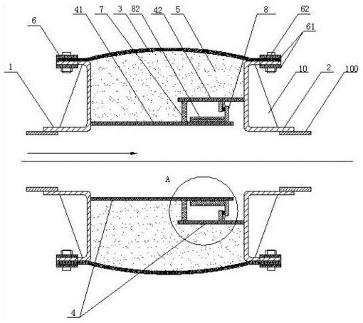
[0031] Such as figure 1 , figure 2 , Figure 4As shown, a non-metallic compensator for a power plant boiler flue gas transmission pipeline includes a left interface bracket 1, a right interface bracket 2, a skin 3, a diversion component 4, a non-metallic heat preservation component 5, and a compression component 6. Wherein, the left and right interface brackets are connected to the smoke discharge pipe 100 . The two ends of the skin are respectively connected to the left interface bracket and the left interface bracket through the pressing assembly 6. The pressing assembly includes a pressing plate 61, bolts and nuts 62; Flow tube 42, one end of the first flow guide tube is fixedly connected to the left interface bracket, and there is a gap between the other end of the first flow guide tube and the right interface bracket; one end of the second flow guide tube is fixedly connected to the right interface bracket Above, there is a gap between the other end of the second guid...

Embodiment 2

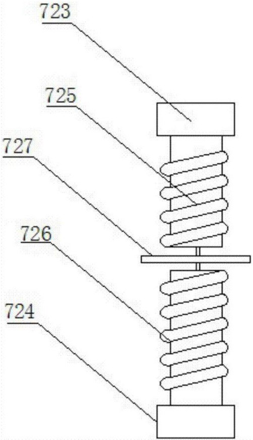
[0040] Such as image 3 As shown, in this embodiment, the elastic assembly includes an upper base 723, a lower base 724, an upper spring 725, a lower spring 726, and a middle connecting piece 727. One end of the upper base is fixedly connected to the second guide tube, and the other end is fixedly connected to The upper spring is detachably connected to the connecting piece, one end of the lower base is fixedly connected to the second guide tube, the other end is fixedly connected to the lower spring, and the lower spring is detachably connected to the middle connecting piece. The detachable connection between the spring and the middle connector is displayed by means of hooks, rings, buckles and the like in the prior art.

[0041] The rest of the structure can adopt the structure of Embodiment 1, which will not be repeated here.

Embodiment 3

[0043] Such as 5, Image 6 As shown, a non-metallic compensator for power plant boiler flue gas transmission pipeline, the non-metallic compensator for power plant boiler flue gas transmission pipeline also includes an auxiliary compensation assembly 9, the auxiliary compensation assembly includes a left vertical plate 91, a right vertical plate 92, a compensation Rod 93; the left vertical plate is vertically connected to the left interface support, and the right vertical plate is vertically connected to the right interface support; between the left vertical plate and the right vertical plate, there are left compensation rod 931, right compensation rod 932, middle compensation rod 933, left compensation rod One end of the left vertical plate is connected, and the other end of the left compensating rod is connected with the middle compensating rod by the pin shaft 94, and the middle compensating rod is connected with an end of the right compensating rod by the pin shaft, and the...


PUM


Abstract

The invention discloses a non-metal compensator for a flue gas conveying pipeline of a power plant boiler. A left connector support, a right connector support, a skin, a flow guiding assembly, a non-metal heat preservation assembly and compression assemblies are included; the two ends of the skin are connected with the left and right connector supports correspondingly through the compression assemblies; the flow guiding assembly comprises a first flow guiding barrel and a second flow guiding barrel which are arranged in a sleeved manner, and an elastic assembly and a waterproof assembly are arranged between the first flow guiding barrel and the second flow guiding barrel; and the space defined by the flow guiding assembly and the skin is filled with the non-metal heat preservation assembly. According to the non-metal compensator for the flue gas conveying pipeline of the power plant boiler, influences of condensed water on the compensator are effectively reduced, the service life of the compensator is prolonged, and the compensation amount of the compensator is increased.

Description

technical field [0001] The invention relates to the field of electric power equipment, in particular to a non-metallic compensator for a power plant boiler flue gas transmission pipeline. Background technique [0002] Power equipment (power system) mainly includes two categories: power generation equipment and power supply equipment. Transformers, contactors, etc. [0003] With the rapid development of my country's economy, power plant boilers are one of our three major power generation equipment and the basic driving force for my country's economic development. In recent years, with the change of thinking on environmental protection and energy saving, a large number of power station boilers with low energy efficiency and heavy pollution have been shut down. At present, driven by positive factors such as the advancement of environmental protection technology, the reduction of power generation costs, and the increase in power demand, the future development prospects of the ...

Claims


Application Information

Patent Timeline
Patent Type & Authority Patents(China)
IPC IPC(8): F16L51/00F23J13/04
CPCF16L51/00F23J13/04
Inventor 朱家浩
Owner 永康市简零贸易有限公司
Why Eureka
Try Eureka