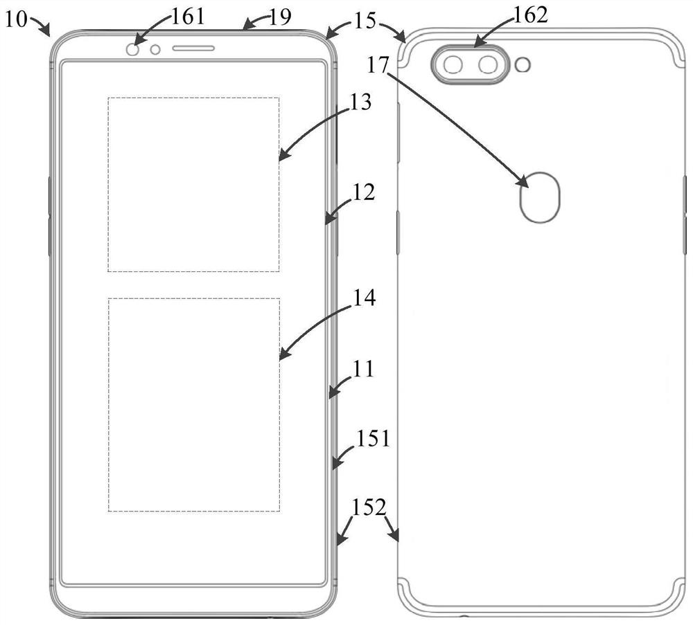
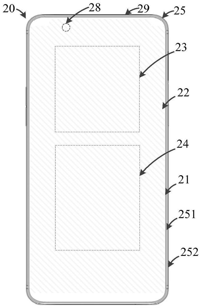
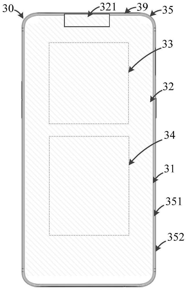
Manufacturing method of antenna assembly, antenna assembly, housing assembly and electronic equipment

An antenna assembly and manufacturing method technology, which is applied to antenna parts, antennas, antenna arrays, etc., can solve the problems of limited space of electronic equipment and increase the size of electronic equipment, and achieve the effect of improving the ability to send and receive information and increasing the clearance area.

Inactive Publication Date: 2020-12-15
GUANGDONG OPPO MOBILE TELECOMM CORP LTD
View PDF4 Cites 0 Cited by
  • Summary
  • Abstract
  • Description
  • Claims
  • Application Information

AI Technical Summary

Problems solved by technology

[0003] However, as the functions of electronic equipment become more and more, the space of electronic equipment becomes more and more limited. Increasing the clearance area of ​​the antenna structure inside the electronic equipment will occupy the space of other devices. If the size of the electronic equipment is not changed, the electronic equipment will be affected. functions, increases the size of the electronic device without affecting the function of the electronic device

Method used


Image

  • Manufacturing method of antenna assembly, antenna assembly, housing assembly and electronic equipment
  • Manufacturing method of antenna assembly, antenna assembly, housing assembly and electronic equipment
  • Manufacturing method of antenna assembly, antenna assembly, housing assembly and electronic equipment

Examples


Embodiment Construction

[0038] The technical solutions in the embodiments of the present application will be clearly and completely described below in conjunction with the drawings in the embodiments of the present application. Apparently, the described embodiments are only some of the embodiments of this application, not all of them. Based on the embodiments in this application, all other embodiments obtained by those skilled in the art without making creative efforts belong to the scope of protection of this application.

[0039] In the description of the present application, it should be understood that the terms "center", "longitudinal", "transverse", "length", "width", "thickness", "upper", "lower", "front", " Orientation indicated by rear, left, right, vertical, horizontal, top, bottom, inside, outside, clockwise, counterclockwise, etc. The positional relationship is based on the orientation or positional relationship shown in the drawings, which is only for the convenience of describing the a...


PUM


Abstract

The embodiment of the invention discloses an antenna module fabrication method, an antenna module, a shell assembly and electronic equipment. The antenna module fabrication method comprises the stepsof providing at least one steel sheet, wherein each steel sheet comprises a first positioning structure; fixing the steel sheet in a mould, wherein the mould comprises a second positioning structure,and the second positioning structure is connected with the first positioning structure to position the steel sheet; performing injection molding on the mould to form a plastic frame, wherein the steelsheet is formed on an outer surface of the plastic frame; and cutting at least one part of the steel sheet and the first positioning structure so that the steel sheet forms an antenna structure. Thesteel sheet and the mould, disclosed by the invention, are fixedly connected by the first positioning structure and the second positioning structure, so that the steel sheet forms the antenna structure, the antenna module in which the antenna structure is formed on the outer surface of the plastic frame by injection molding is obtained, and the clearance region of the antenna structure under the condition that the size of the electronic equipment can be expanded.

Description

technical field [0001] The present application relates to the technical field of electronic equipment, and in particular to a manufacturing method of an antenna assembly, an antenna assembly, a casing assembly and electronic equipment. Background technique [0002] With the development of communication technology, electronic devices such as smartphones are becoming more and more popular. During the use of electronic equipment, such as using electronic equipment to talk. In order to improve the call quality, the clearance area of ​​the antenna structure can be increased inside the electronic device. [0003] However, with more and more functions of electronic equipment, the space of electronic equipment is becoming more and more limited. Increasing the clearance area of ​​the antenna structure inside the electronic equipment will occupy the space of other devices. If the size of the electronic equipment is not changed, the electronic equipment will be affected. The function...

Claims


Application Information

Patent Timeline
Patent Type & Authority Patents(China)
IPC IPC(8): H01Q1/36H01Q21/00H01Q1/22H01Q1/24H04M1/18
CPCH01Q1/22H01Q1/2258H01Q1/242H01Q1/36H01Q21/00H04M1/18
Inventor 李飞飞
Owner GUANGDONG OPPO MOBILE TELECOMM CORP LTD
Why Eureka
Try Eureka