Manufacturing method of antenna assembly, antenna assembly and electronic equipment

An antenna assembly and manufacturing method technology, applied in the field of electronic equipment, can solve problems such as the impact of waterproof and reliability of the whole machine, affecting user experience, etc., and achieve the effect of improving the ability to send and receive information, ensuring width, waterproofness and reliability.

Active Publication Date: 2021-01-08
XIAN YIPU COMM TECH
View PDF13 Cites 0 Cited by
  • Summary
  • Abstract
  • Description
  • Claims
  • Application Information

AI Technical Summary

Problems solved by technology

[0004]However, with the gradual improvement of the quality of life, people have higher and higher requirements for the appearance and performance of mobile terminals, such as the limit requirements of screen ratio and various With the continuous improvement of communication modules, etc., the width of the dispensing surface between the display and the body and the size of the antenna clearance area are challenged. Without an effective dispensing surface width, the waterproof and reliability of the whole machine will be seriously affected, directly affecting In order to improve the user experience, it is necessary to increase the antenna clearance area and ensure the width of the dispensing surface to become a major problem that needs to be solved urgently.

Method used


Image

  • Manufacturing method of antenna assembly, antenna assembly and electronic equipment
  • Manufacturing method of antenna assembly, antenna assembly and electronic equipment
  • Manufacturing method of antenna assembly, antenna assembly and electronic equipment

Examples


Embodiment 1

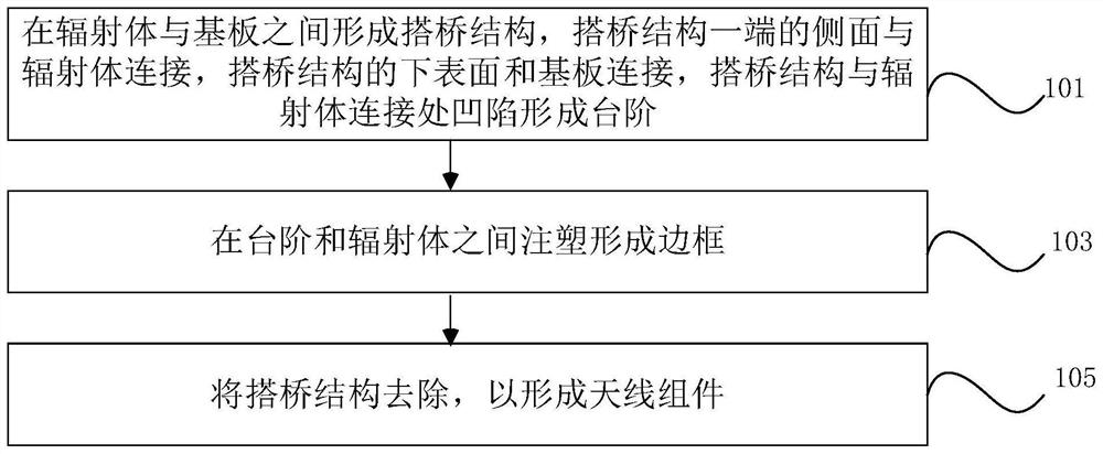
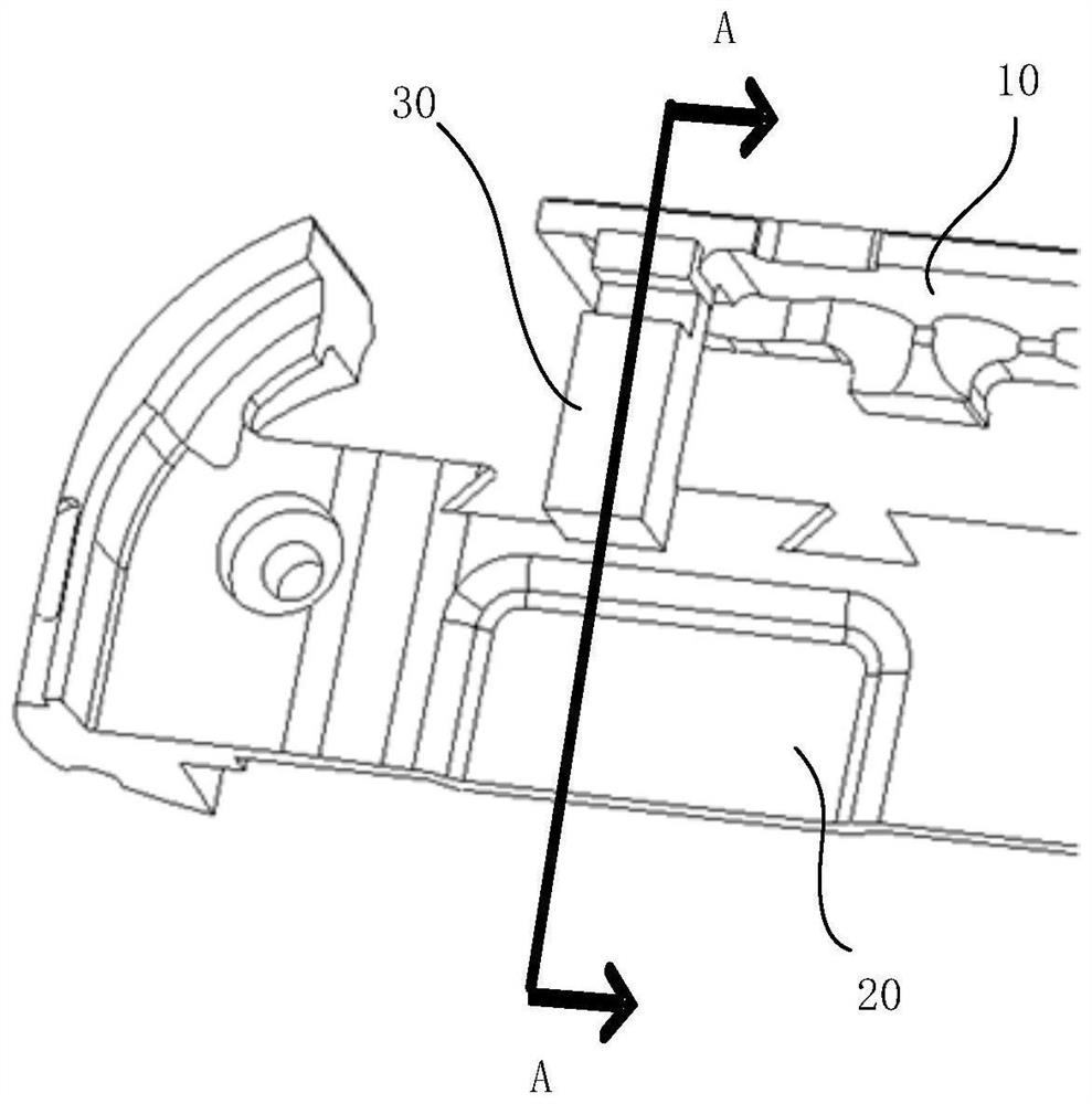
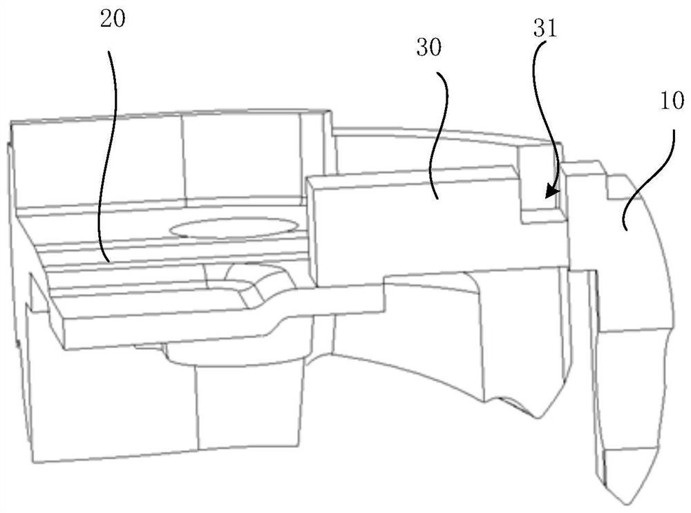
[0059] figure 1 It is a schematic flowchart of a method for manufacturing an antenna assembly provided by an embodiment of the present invention, figure 2 It is a schematic structural diagram of the connection between the radiator and the substrate in a method for manufacturing an antenna assembly provided by an embodiment of the present invention, image 3 for figure 2 A cross-sectional view of the radiator-to-substrate connection along section line A provided in , Figure 4 It is a schematic structural diagram of the connection between the radiator, the substrate and the frame in a method for manufacturing an antenna assembly provided by an embodiment of the present invention, Figure 5 for Figure 4 The cross-sectional view of the radiator, substrate and frame connection along the cutting line B provided in Image 6 It is a schematic diagram of the structure of the radiator, the substrate and the frame after the bridging structure is removed in the method of manufactu...

Embodiment 2

[0122] Another aspect of the embodiments of the present invention provides an antenna assembly, which is manufactured by using the manufacturing method of the antenna assembly provided in the first embodiment.

[0123] The antenna assembly provided by the embodiment of the present invention is made by the manufacturing method of the assembly provided by Embodiment 1, which can increase the clearance area of ​​the antenna structure and improve the ability of the antenna structure to send and receive information without changing the size of the electronic device. Can effectively guarantee the width of the dispensing surface.

Embodiment 3

[0125] Another aspect of the present invention provides an electronic device, including the antenna assembly and the control circuit provided in Embodiment 2, wherein the antenna assembly and the control circuit are electrically connected.

[0126] The electronic device may include: a cover plate, a display screen, a control circuit, a battery, a housing, front and rear cameras, an unlocking module, an antenna assembly, and the like.

[0127] Wherein, the cover plate is installed on the display screen to cover the display screen, and the cover plate may be a transparent glass cover plate so that the display screen can be displayed through the cover plate.

[0128] The housing can form the outer contour of the electronic device. In some embodiments of the present invention, the housing can include a middle frame and a rear cover, the middle frame and the rear cover are combined to form a housing, and the middle frame and the rear cover can form a storage space for Storage contr...


PUM


Abstract

The embodiment of the invention provides an antenna assembly manufacturing method, an antenna assembly and electronic equipment. The method comprises the steps that a bridging structure is formed between a radiator and a substrate, the side surface of one end of the bridging structure is connected with the radiator, the lower surface of the bridging structure is connected with the substrate, the connection part of the bridging structure and the radiator is recessed to form a step, a frame is injection-molded at the step, and the bridging structure is removed to form the antenna assembly. According to the manufacturing method of the antenna assembly, the antenna assembly and the electronic equipment provided by the invention, the clearance area of the antenna structure can be increased without changing the size of the electronic equipment, and the width of the dispensing surface can be effectively ensured, so that the waterproofness and reliability of the whole machine are further enhanced.

Description

technical field [0001] The invention relates to the technical field of electronic equipment, in particular to a method for manufacturing an antenna component, the antenna component and electronic equipment. Background technique [0002] With the continuous development of communication technology, Long Term Evolution (LET) communication has become popular all over the world. At the same time, Sub6G, 5G SA, and millimeter wave communication technologies have emerged in our lives. The carriers on which information is sent and received It is the antenna. The antenna is a converter of high-frequency electrical signals and wireless electromagnetic waves. It can convert high-frequency current into wireless electromagnetic waves to radiate to distant places, and at the same time transmit the information carried in electromagnetic waves to distant places. At the same time, the antenna can also convert the electromagnetic wave signal propagated in space into a high-frequency current s...

Claims


Application Information

Patent Timeline
Patent Type & Authority Applications(China)
IPC IPC(8): H01Q1/36
CPCH01Q1/36
Inventor 佘小栋解颖轩张超王维涛胡万利陈林吴泳峰郝晓培
Owner XIAN YIPU COMM TECH
Why Eureka
Try Eureka