Circulation flow reactor

A loop reactor, reactor technology, applied in chemical/physical/physical-chemical stationary reactors, chemical instruments and methods, mixers, etc. problem, to achieve the effect of good mixing effect, increasing cooling area and short reaction time

Pending Publication Date: 2018-10-02
NANTONG HAIERMA TECH CO LTD
View PDF0 Cites 0 Cited by
  • Summary
  • Abstract
  • Description
  • Claims
  • Application Information

AI Technical Summary

Problems solved by technology

The reaction process of the reactor consumes a lot of energy, the reactio

Method used


Image

  • Circulation flow reactor

Examples


Embodiment 1

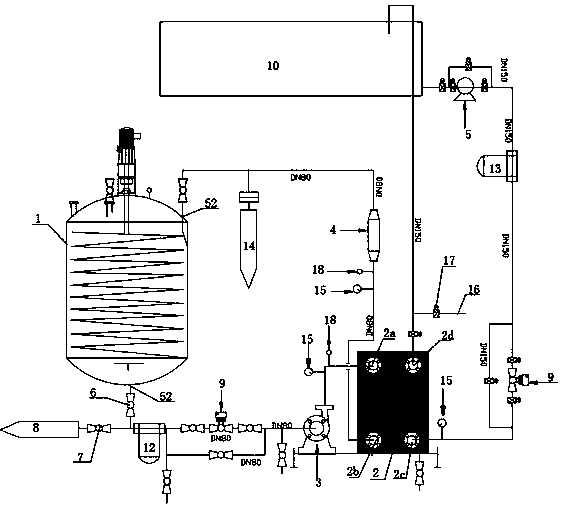
[0020] Such as figure 1 As shown, it is a loop reactor of the present invention, comprising a reactor 1, a heat exchanger 2, an oil delivery pump 3, a static mixer 4 and a cooling water pump 5; the bottom of the reactor 5 is provided with a material outlet 51, and the top is provided with a cooling material The inlet 52; the material outlet 51 is connected to the pressure tank 8 through the switch valve one 6, the switch valve two 7 and the pipeline; the material outlet 51 is connected with the oil pump 3 through the switch valve one 6, the pneumatic regulating valve 9 and the pipeline; the switch valve one 6 A material filter 12 is set between the oil pump 3; the heat exchanger 2 is provided with an oil inlet 2a, an oil outlet 2b, a water inlet 2c and a water outlet 2d; the oil inlet 2a is connected to the oil pump 3 through a pipeline; The oil port 2b is connected by the feed port of the pipeline static mixer 4; the discharge port of the static mixer 4 is connected with the ...


PUM


Abstract

The invention discloses a circulation flow reactor which comprises a reaction kettle, a heat exchanger, an oil transfer pump, a static mixer and a cooling water pump. The reaction kettle, the oil transfer pump, the heat exchanger and the static mixer are connected through a pipeline to form a material circulation loop; the heat exchanger, the cooling water pump and a workshop water feeding tank are connected through a water pipe to form a cooling water circulation loop; materials in the material circulation loop and cooling water in the cooling water circulation loop exchange heat in the heatexchanger. By the aid of the circulation flow reactor, production and product quality are improved, and safety coefficient is improved.

Description

technical field [0001] The invention relates to the technical field of chemical production equipment, in particular to a loop reactor. Background technique [0002] Most of the existing epoxidized soybean oil production adopts reactor stirring, and reacts through internal coil cooling. The reaction process of the reactor consumes a lot of energy, the reaction time is long, and the reaction temperature fluctuates in a large range. Contents of the invention [0003] The technical problem to be solved by the invention is to provide a loop reactor, shorten the reaction time, and improve the output and product quality. [0004] In order to solve the above-mentioned technical problems, the present invention adopts the following technical solutions: a loop reactor, including a reactor, a heat exchanger, an oil pump, a static mixer and a cooling water pump; the reactor, the oil pump, the heat exchanger, The static mixer is connected by pipes to form a material circulation loop; ...

Claims


Application Information

Patent Timeline
IPC IPC(8): B01J19/18B01F13/10C07D301/03C07D303/42
CPCB01J19/0013B01J19/0053B01J19/1881C07D301/03C07D303/42B01J2219/00103B01F33/821
Inventor 徐健曹志亮杜烨
Owner NANTONG HAIERMA TECH CO LTD
Why Eureka
Try Eureka