Portable safe tool box
A toolbox and portable technology, which is applied in the field of portable safety toolboxes, can solve the problems of loose holding of tools, inconvenient access to tools, and insufficient portability, etc., and achieve convenient access to small parts, easy access to tools, and convenient portability Effect
- Summary
- Abstract
- Description
- Claims
- Application Information
AI Technical Summary
Problems solved by technology
Method used
Image
Examples
Embodiment 1
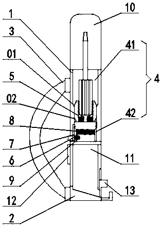
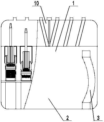
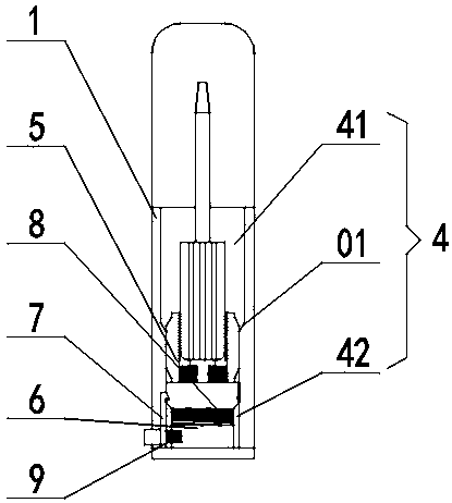
[0036] A portable safety toolbox, such as Figure 1-3 As shown, it includes an upper box body 1 and a lower box body 2 that are connected in sequence from top to bottom. A strap 3 is connected between the outer wall of the upper box body 1 and the outer wall of the lower box body 2. The upper box body 1 From left to right, the interior is divided into a number of cavities 4 with bosses 6 mounted on the bottom surface by partitions. The cavities 4 include relaxation cavities 41 and clamps arranged coaxially from top to bottom with inner diameters from large to small. In the cavity 42, the slack cavity 41 and the clamping cavity 42 are provided with a squeeze chamfer 01 at the transition point; the clamping cavity 42 is equipped with an elastic clamping member 5, which can be clamped The holding cavity 42 and the relaxation cavity 41 slide back and forth; the bottom of the elastic clamping member 5 is connected to the top of the boss 6 through the first spring 8, and the outer low...
Embodiment 2
[0043] This embodiment is further optimized on the basis of embodiment 1, such as Figure 4-5 As shown, the elastic clamping member 5 includes a base 51, a petal-shaped chuck 52, a compression spring 53, and a T-shaped stand 54. The diameter of the base 51 is equal to the cavity diameter of the clamping cavity 42, and the diameter of the base 51 A T-shaped stand 54 is fixedly connected to the center of the upper surface, and the lower side of the base 51 is movably clamped with the upper end of the locking member 7; the lower part of the T-shaped stand 54 extends to the edge of the upper surface of the base 51. A number of radial sliding grooves 511, in which a petal-shaped chuck 52 is slidably installed; the inner lower part of the petal-shaped chuck 52 is connected to the lower part of the T-shaped stand 54 through a compression spring 53, and the petal-shaped chuck The inner surface of the head 52 is provided with an elastic material layer.
[0044] A T-shaped stand 54 is fix...
Embodiment 3
[0047] This embodiment is further optimized on the basis of embodiment 1 and embodiment 2, such as Image 6 As shown, the locking member 7 includes a buckle 71 and a button 72 installed on the lower part of the inner wall of the clamping cavity 42. The lower outside of the buckle 71 is connected to one end of the button 72, and the other end of the button 72 is located at The outer side of the cavity wall of the clamping cavity 42 and the lower inner side of the buckle lock 71 are connected to the side surface of the boss 6 through the second spring 9; the lower end side of the elastic clamping member 5 is provided with a matching buckle lock 71 The buckle lock slot.
[0048] When the locking groove on the lower end side of the elastic clamping member 5 is engaged with the buckle lock 71, the elastic clamping member 5 is in a locked state; when the elastic clamping member 5 needs to be released, press the button 72 to force the lower end of the buckle lock 71 to press At this tim...
PUM
 Abstract
Description
Claims
Application Information
 - R&D
- Intellectual Property
- Life Sciences
- Materials
- Tech Scout
- Unparalleled Data Quality
- Higher Quality Content
- 60% Fewer Hallucinations
Browse by: Latest US Patents, China's latest patents, Technical Efficacy Thesaurus, Application Domain, Technology Topic, Popular Technical Reports.
© 2025 PatSnap. All rights reserved.Legal|Privacy policy|Modern Slavery Act Transparency Statement|Sitemap|About US| Contact US: help@patsnap.com


