Optical fiber switch node sensor

A switching node and sensor technology, applied in the field of optical sensing, can solve the problems of reduced capacity expansion of optical fiber networks, difficulty in finding a communication room, and reduced size of base station equipment.

Pending Publication Date: 2018-10-16
KUNSHAN JINMING PHOTOELECTRIC SCI & TECH
View PDF2 Cites 2 Cited by
  • Summary
  • Abstract
  • Description
  • Claims
  • Application Information

AI Technical Summary

Problems solved by technology

[0005] However, the signal analysis equipment used to process reflected light signals can only judge the opening and closing status of the door leaf of a single optical cable junction box by the presence or absence of reflected light in the optical fiber.
This results in the need to use a large number of idle optical fiber resources in practical applications to complete the monitoring of the opening and closing status of the door pages of multiple optical cable transfer boxes, which in turn leads to the deployment of optical fiber sensing systems that may reduce the expansion capacity of telecom operators' optical fiber networks
[0006] Due to the reduction in the size of base station equipment in recent years, the number of communication equipment rooms has become less and less, making it difficult to find enough communication equipment rooms to place nearby signal analysis equipment for processing reflected optical signals

Method used


Image

  • Optical fiber switch node sensor
  • Optical fiber switch node sensor
  • Optical fiber switch node sensor

Examples


Embodiment 1

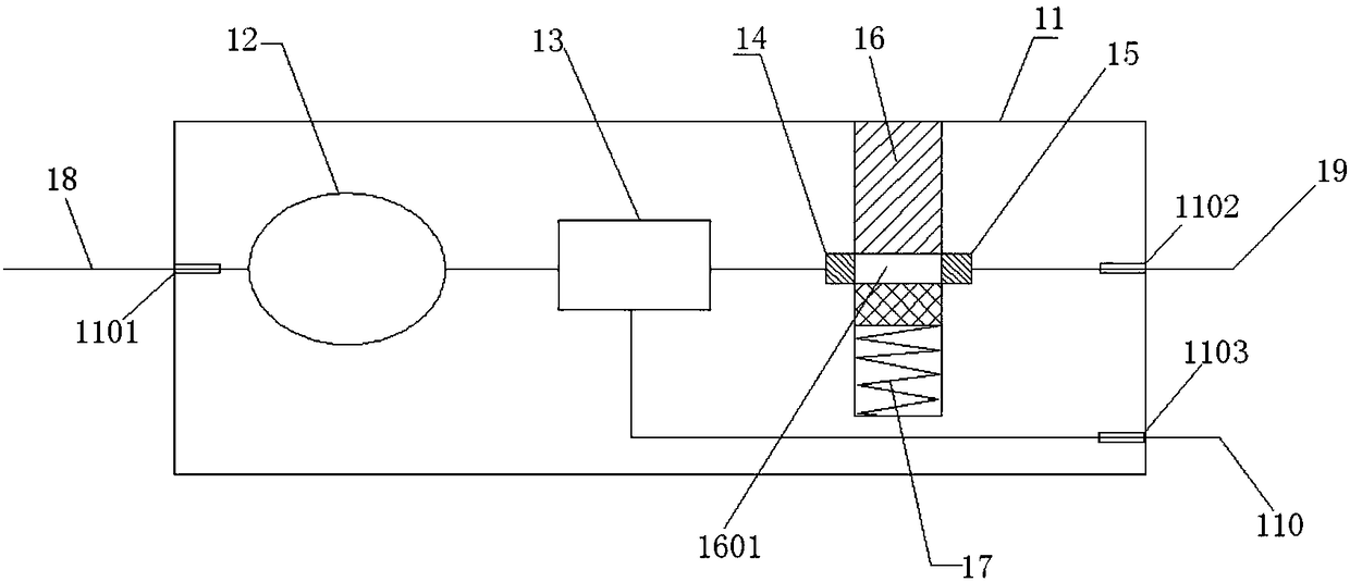
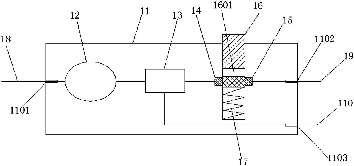
[0028] Such as figure 1 and figure 2As shown, an optical fiber switch node sensor includes a sensor body 11, an optical fiber tray 12, an optical fiber splitter 13, a first optical fiber collimator 14, a second optical fiber collimator 15, a movable slider 16, and an elastic member 17 , the sensor body has a first port 1101 for the access of the upper optical fiber 18, a second port 1102 for the access of the local optical fiber 19 and a third port 1103 for the access of the lower optical fiber 110, the first The fiber collimator and the second fiber collimator are accommodated and positioned in the sensor body at a predetermined distance, and the first fiber collimator and the second fiber collimator realize Gaussian beam coupling; After passing through the first port, the upper-level optical fiber passes through the fiber entrance of the fiber optic disk box and coils the fiber to a set length, then passes out from the fiber outlet of the fiber optic disk box, and then ent...

Embodiment 2

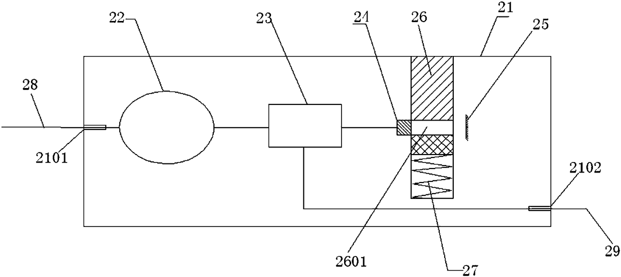
[0042] Such as image 3 and Figure 4As shown, a kind of optical fiber switch node sensor, comprises sensor body 21, optical fiber disk fiber box 22, optical fiber beam splitter 23, first optical fiber collimator 24, light reflector 25, movable slider 26, elastic member 27, described The sensor body has a first port 2101 for the access of the upper-level optical fiber 28 and a second port 2102 for the access of the lower-level optical fiber 29. The first optical fiber collimator and the optical reflector are separated by a set distance Positioned in the sensor body, and the central axis of the first optical fiber collimator is perpendicular to the light reflector; the upper-level optical fiber passes through the first port and passes through the optical fiber entrance of the optical fiber tray and After the length of the fiber is set, it passes through the fiber outlet of the fiber optic box, and then is connected to the input end of the optical fiber splitter; the optical fi...


PUM


Abstract

The invention discloses an optical fiber switch node sensor, which comprises a sensor body, an optical fiber coiling box, an optical fiber beam splitter, a first optical fiber collimator, a second optical fiber collimator, a movable sliding block and an elastic part, wherein the sensor body is provided with a first port accessed by an upper-level optical fiber, a second port accessed by a local optical fiber, and a third port accessed by a lower-level optical fiber. The optical fiber coiling box is provided, so that the time slot between back pulse light is increased. Optical paths are separated by arranging the optical fiber beam splitter, and more node sensors can be connected, so as to form a plurality of optical cable cross-connection cabinet networks. The first and second optical fiber collimators are connected with the optical fiber beam splitter and the local optical fiber, and a movable sliding block and an elastic piece are arranged between the two optical fiber collimators. Mechanical control of the on-off state of the back pulse light can be realized. The optical fiber switch node sensor serves as a sensing node, the switch states of the plurality of monitored optical cable cross-connection cabinets are monitored at the same time through a signal analysis device under passive condition after the sensing network is established.

Description

technical field [0001] The invention relates to the technical field of optical sensing, in particular to an optical fiber switch node sensor. Background technique [0002] The optical cable transfer box is a transfer device that provides optical cable termination and jumper connection for the backbone layer optical cable and the distribution layer optical cable. After the optical cable is introduced into the optical cable transfer box, after being fixed, terminated, and distributed, the backbone layer optical cable and the distribution layer optical cable are connected using a jumper fiber. It is mainly used in the optical cable communication network to connect the main optical cable and the branch optical cable, and to terminate, protect, connect and dispatch and manage the optical cable and optical fiber. [0003] With the promotion of TTX network technology and the expansion of various data services, operators have installed a large number of optical cable transfer boxes...

Claims


Application Information

Patent Timeline
Patent Type & Authority Applications(China)
IPC IPC(8): G01D5/26G01V8/16
CPCG01D5/268G01V8/16
Inventor 曹孟辉王雪峰
Owner KUNSHAN JINMING PHOTOELECTRIC SCI & TECH
Why Eureka
Try Eureka