Detection and control circuit and detection method of electric vehicle high voltage circuit

A high-voltage circuit and electric vehicle technology, which is applied to electric vehicles, electrical devices, vehicle components, etc., can solve problems such as the inability to control the safety of high-voltage contactors

Pending Publication Date: 2018-11-13
四川江淮汽车有限公司
0 Cites 8 Cited by

AI-Extracted Technical Summary

Problems solved by technology

[0004] The purpose of the present invention is to: aim at the above technical problems, to provide a high-voltage circuit detection and control circuit for electric vehicles, so as to realize the collection of fuse...

Method used

Specifically, as shown in Figure 2, the electric vehicle high-voltage circuit of the present embodiment is provided with a maintenance switch MSD on the positive pole circuit of the power battery pack, and a main fuse is provided inside the maintenance switch MSD for implementing Short circuit protection. A current sensor and a main negative contactor are installed in the negative main circuit of the power battery pack. The battery management module BMS is connected to the current sensor through a wire to detect the current of the entire circuit. The battery management module BMS is directly connected to the main negative contactor through a wire. The coils are connected, and the battery management module BMS directly controls the main negative contactor to avoid bat...

Abstract

The invention discloses a detection and control circuit and detection method of an electric vehicle high voltage circuit. The detection and control circuit comprises a plurality of high voltage devices, a battery management module, a high voltage control module and a vehicle control unit, wherein each high voltage device is connected with a contactor and/or a fuse; the battery management module isused for enabling a main negative contactor and generating main negative contactor enabling signals; the high voltage control module is used for detecting the voltage at the back end of each fuse andgenerating the fuse detection signals, detecting the voltage at the back end of each auxiliary contact of each contactor and generating the contactor contact detection signals, and enabling each contactor except the main negative contactor and generating the contactor enabling signals; and the vehicle control unit is used for judging the working state of the fuses and the contactors according tothe obtained fuse detection signals, the contactor contact signals, the contactor enabling signals and the main negative contactor enabling signals. The detection and control circuit of the electric vehicle high voltage circuit solves the problem of misjudging the contactors as abnormal when the fuses are fused, and can accurately judge the working states of the contactors.

Application Domain

Electric devices

Technology Topic

ContactorElectrical battery +8

Image

  • Detection and control circuit and detection method of electric vehicle high voltage circuit
  • Detection and control circuit and detection method of electric vehicle high voltage circuit
  • Detection and control circuit and detection method of electric vehicle high voltage circuit

Examples

  • Experimental program(1)

Example Embodiment

[0041] In order to make the object, technical solution and advantages of the present invention clearer, the present invention will be further described in detail below in conjunction with the accompanying drawings and embodiments. It should be understood that the specific embodiments described here are only used to explain the present invention, and are not intended to limit the present invention, that is, the described embodiments are only some of the embodiments of the present invention, but not all of the embodiments. The components of the embodiments of the invention generally described and illustrated in the figures herein may be arranged and designed in a variety of different configurations.
[0042] Accordingly, the following detailed description of the embodiments of the invention provided in the accompanying drawings is not intended to limit the scope of the claimed invention, but merely represents selected embodiments of the invention. Based on the embodiments of the present invention, all other embodiments obtained by those skilled in the art without making creative efforts belong to the protection scope of the present invention.
[0043] It should be noted that relative terms such as the terms "first" and "second" are only used to distinguish one entity or operation from another entity or operation, and do not necessarily require or imply any relationship between these entities or operations. There is no such actual relationship or order between them. Furthermore, the term "comprises", "comprises" or any other variation thereof is intended to cover a non-exclusive inclusion such that a process, method, article, or apparatus comprising a set of elements includes not only those elements, but also includes elements not expressly listed. other elements of or also include elements inherent in such a process, method, article, or device. Without further limitations, an element defined by the phrase "comprising a ..." does not exclude the presence of additional identical elements in the process, method, article or apparatus comprising said element.
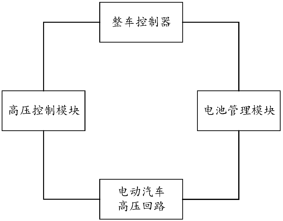
[0044] A high-voltage circuit detection and control circuit for an electric vehicle in this embodiment includes: a plurality of high-voltage devices; each of the high-voltage devices is connected with a contactor and/or a fuse;
[0045] A battery management module, the battery management module is connected to the coil of the main negative contactor, and is used to enable the main negative contactor and generate a main negative contactor enabling signal;
[0046]The high-voltage control module is used to detect the back-end voltage of each fuse and generate a fuse detection signal, as well as detect the auxiliary contact rear-end voltage of each contactor and generate a contactor contact detection signal, and control the main negative contactor Each contactor outside is enabled and generates a contactor enable signal;
[0047] The vehicle controller is used to judge the operation of each fuse and contactor in the high-voltage circuit according to the acquired fuse detection signal, contactor contact signal, contactor enable signal and main-negative contactor enable signal state.
[0048] A method for detecting a high-voltage circuit of an electric vehicle in this embodiment specifically includes the following steps:
[0049] S1. Detect the voltage at the rear end of the fuse to generate a fuse detection signal;
[0050] S2. Detect the rear-end voltage of the auxiliary contact of the contactor to generate a contactor detection signal;
[0051] S3. Detecting the enabling of the contactor to generate a contactor enabling signal;
[0052] S4. Determine whether the fuse is blown according to the fuse detection signal;
[0053] S5. When judging that the fuse is not blown, judge the working state of the contactor according to the contactor detection signal and the contactor enabling signal; specifically,
[0054] If there is no contactor enable signal, and the contactor detection signal is not high level, it is judged that the contactor is in the disconnected state;
[0055] There is a contactor enable signal, and the contactor detection signal is high level, judging that the contactor is in a closed state;
[0056] There is no contactor enable signal, and the contactor detection signal is high level, judging that the contactor is in a sticking state;
[0057] If there is a contactor enabling signal and the contactor detection signal is not high level, it is judged that the contactor is in an abnormal state.
[0058] In the above electric vehicle high-voltage circuit detection and control method, there is at least no sequence relationship between steps S1, S2 and S3, which can be performed simultaneously or one after the other, and the order of execution should not be determined by the number before the steps.
[0059] This technical solution correctly judges the working state of the contactor by collecting the fuse detection signal of the high-voltage device and the contactor contact signal, so as to avoid the problem of wrongly judging that the contactor is abnormal when the fuse is blown, and can accurately It can accurately reflect whether each fuse in the high-voltage circuit is blown, and better distinguish the working status of each contactor in the high-voltage circuit, and accurately judge the disconnection, closure, adhesion, and abnormal status of the contactor. Through the analysis of these information Acquisition can better judge the working status of the vehicle, which is convenient for the vehicle controller VCU to better manage the vehicle and perform fault diagnosis.
[0060] Specifically, such as figure 2 As shown, the high-voltage circuit of the electric vehicle in this embodiment is provided with a maintenance switch MSD on the positive circuit of the power battery pack, and a main fuse is provided inside the maintenance switch MSD for short-circuit protection of the entire circuit. A current sensor and a main negative contactor are installed in the negative main circuit of the power battery pack. The battery management module BMS is connected to the current sensor through a wire to detect the current of the entire circuit. The battery management module BMS is directly connected to the main negative contactor through a wire. The coils are connected, and the battery management module BMS directly controls the main negative contactor to avoid battery abuse and excessive discharge.
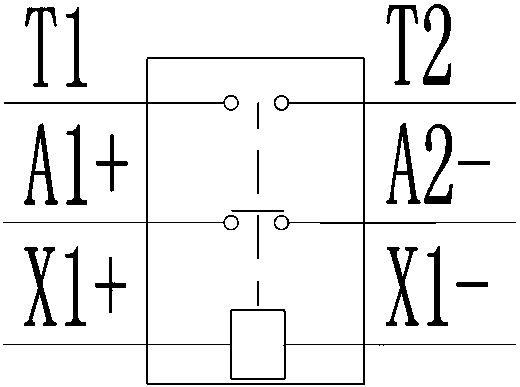
[0061] The main high-voltage devices in the high-voltage circuit of the electric vehicle in this embodiment include a motor controller, an air-conditioning compressor, a PTC warm air heater, an air pump controller, an oil pump controller, a DCDC converter, a DC charging socket and a battery heating socket; The contactor of the high voltage device adopts such as image 3 The high-voltage DC contactor with auxiliary contacts shown includes the main drive contactor, PTC contactor, DCDC contactor, direct charging contactor, heating contactor, and main negative contactor. While the pre-charge contactor adopts such as Figure 4 The high-voltage DC contactor shown includes the main drive pre-charging contactor and DCDC pre-charging contactor. The fuses include: a first fuse FS1 , a second fuse FS2 , a third fuse FS3 , a fourth fuse FS4 , a fifth fuse FS5 and a main fuse provided inside the maintenance switch MSD. The negative pole of each main high-voltage device is connected to the A2-end of the main negative contactor; the positive pole of the motor controller is connected to the A2-end of the main drive contactor; the positive pole of the PTC warm air heater Connect to the A2- terminal of the PTC contactor; the A1+ terminal of the PTC contactor and the positive pole of the air conditioner compressor are both connected to one end of the first fuse FS1; the positive pole of the air pump controller is connected to the second fuse One end of FS2; the positive pole of the oil pump controller is connected to one end of the third fuse FS3; the other end of the first fuse FS1, the other end of the second fuse FS2 and the other end of the third fuse FS3 are all Connect to the A2-end of the main drive contactor; the positive pole of the DCDC converter is connected to one end of the fourth fuse FS4; the main contact of the DCDC pre-charging contactor is connected in parallel with the main contact of the DCDC contactor A DCDC loop precharging circuit is formed, one end of the DCDC loop precharging circuit is connected to the other end of the fourth fuse; the other end of the DCDC loop precharging circuit is connected to the A2-end of the main drive contactor; the DC charging socket The positive pole of the battery heating socket is connected to the A2- terminal of the direct charging contactor, and the A1+ terminal of the direct charging contactor is connected to the A2- terminal of the main drive contactor; the positive pole of the battery heating socket is connected to the fifth fuse One end of FS5; the other end of the fifth fuse FS5 is connected to the A2-end of the heating contactor; the A1+ end of the heating contactor is connected to the A2-end of the main drive contactor; the main drive pre- The main contact of the charging contactor and the main contact of the main drive contactor are connected in parallel to form a high-voltage circuit pre-charging circuit; one end of the high-voltage circuit pre-charging circuit is connected to one end of the MSD. In this embodiment, the main contact of the main drive pre-charging contactor is preferably connected in series with the first voltage regulator transistor D1 and the first pre-charging resistance R1, and the DCDC pre-charging contactor is connected with the second voltage regulator transistor D2 and the second The pre-charging resistor R2 is connected in series, and the voltage regulator and the pre-charging resistor are used to stabilize the voltage and limit the current of the pre-charging circuit to ensure the safety of pre-charging.
[0062] A high-voltage circuit detection and control circuit for an electric vehicle provided by a preferred embodiment of the present invention includes: a vehicle controller VCU, a battery management module BMS, and a high-voltage control module; the high-voltage control module is arranged in a separate high-voltage distribution box Or inside the all-in-one power controller, which includes a voltage detection module, a digital input acquisition module, a contactor drive module, and a communication module; the communication modules of the vehicle controller VCU, battery management module BMS, and high-voltage control module pass CAN Bus connection; the vehicle controller obtains the fuse detection signal, contactor contact signal, contactor enable signal and main negative contactor enable signal through the CAN bus. For better distinction and description, the voltage detection module of this embodiment is as follows figure 2 As shown, it includes a first-way voltage detection module and a second-way voltage detection module; the first-way voltage detection module is provided with A-terminal, A1-terminal, A2-terminal and A3-terminal, and the second-way voltage detection module is provided with a B-terminal - terminal, B4 terminal, B5 terminal, B6 terminal, B7 terminal and B8 terminal; And described digital quantity input acquisition module is provided with port 1, port 2, port 3, port 4, port 5 and port 6; Described contactor The drive module is provided with port 1 , port 2 , port 3 , port 4 , port 5 , port 6 and port 7 .
[0063] The voltage detection module is used to connect the rear end of each fuse in the high-voltage circuit, detect the voltage at the rear end of each fuse and generate a fuse detection signal. Specifically, the A1 end of the first voltage detection module is connected to one end of the fifth fuse FS5, and the A3 end is connected to one end of the maintenance switch MSD; the B4 end of the second voltage detection module is connected to the first One end of four fuses FS4, B5 end is connected to one end of the third fuse FS3, B6 end is connected to one end of the second fuse FS2, B7 end is connected to one end of the first fuse FS1, B8 end is connected to the main drive contact device A2-terminal.
[0064] Judgment principle of fuse state in high voltage circuit:
[0065] (1) When the main negative contactor is normally closed, no normal voltage value can be detected at the A3 terminal of the first voltage detection module, and it is judged that the main fuse inside the maintenance switch MSD is blown;
[0066] (2) When the main negative contactor and the main drive contactor are normally closed, no normal voltage value can be detected at the B7 terminal of the second voltage detection module, and it is judged that the first fuse shared by the air conditioner compressor and the PTC heater circuit is broken Device FS1 fuse;
[0067] (3) When the main negative contactor and the main drive contactor are normally closed, no normal voltage value can be detected at the B6 terminal of the second voltage detection module, and it is judged that the second fuse FS2 of the air pump circuit is blown;
[0068] (4) When the main negative contactor and the main drive contactor are normally closed, no normal voltage value can be detected at the B5 terminal of the second voltage detection module, and it is judged that the third fuse FS3 of the oil pump circuit is blown;
[0069] (5) When the main negative contactor and the DCDC contactor are normally closed, the B4 terminal of the second voltage detection module detects that there is no normal voltage value, and it is judged that the fourth fuse FS4 of the DCDC circuit is blown;
[0070] (6) When the main negative contactor and the heating contactor are normally closed, no normal voltage value can be detected at the A1 terminal of the first voltage detection module, and it is judged that the fifth fuse FS5 of the heating circuit is blown.
[0071] The coil front end and auxiliary contact front end of each contactor in the high-voltage circuit are connected to the +12V power supply of the vehicle, that is, the X1+ end of the main drive pre-charge contactor, the X1+ end of the main drive contactor, the X1+ end of the PTC contactor, The X1+ terminal of the DCDC pre-charging contactor, the X1+ terminal of the DCDC contactor, the X1+ terminal of the direct charging contactor and the X1+ terminal of the heating contactor, and the T1 terminal of the main drive contactor, the T1 terminal of the PTC contactor, and the DCDC contactor The T1 terminal of the battery, the T1 terminal of the direct charging contactor, the T1 terminal of the heating contactor and the T1 terminal of the main negative contactor are all connected to the +12V power supply of the vehicle.
[0072] The digital input acquisition module is used to connect the rear end of the auxiliary contact of each contactor in the high-voltage circuit, detect the voltage of the rear end of the auxiliary contact of each contactor and generate a contactor contact detection signal. Specifically, port 1 of the digital input acquisition module is connected to the T2 terminal of the main negative contactor, port 2 is connected to the T2 terminal of the heating contactor, port 3 is connected to the T2 terminal of the DC contactor, and port 4 is connected to the DCDC For the T2 terminal of the contactor, port 5 is connected to the T2 terminal of the PTC contactor, and port 6 is connected to the T2 terminal of the main drive contactor;
[0073] The battery management module BMS is connected to the coil of the main negative contactor for enabling the main negative contactor, and sends a main negative contactor enabling signal to the vehicle controller.
[0074] The contactor driving module is used to connect the coils of each contactor except the main negative driver in the high-voltage circuit, enable each contactor except the main negative contactor and generate a contactor enabling signal. Specifically, port 1 of the contactor drive module is connected to the X1-end of the heating contactor, port 2 is connected to the X1-end of the direct charging contactor, port 3 is connected to the X1-end of the DCDC contactor, and port 4 is connected to To the X1-terminal of the DCDC pre-charge contactor, port 5 is connected to the X1-terminal of the PTC contactor, port 6 is connected to the X1-terminal of the main drive contactor, and port 7 is connected to the X1-terminal of the main drive pre-charge contactor .
[0075] When the fuse in the high-voltage circuit is not blown, the principle of judging the working state of the corresponding contactor:
[0076] (1) Determine the working status of the main and negative contactors. The battery management module BMS is directly connected to the coil of the main negative contactor, so it can directly enable the main negative contactor, and the working status of the main negative contactor can be determined by combining the level signal collected by port 1 of the digital input acquisition module. judge. specifically,
[0077] When the battery management module BMS does not enable the main negative contactor coil, and the port 1 of the digital input acquisition module does not collect +12V high level, the main negative contactor is disconnected;
[0078] When the battery management module BMS enables the main negative contactor coil, and the port 1 of the digital input acquisition module collects a high level of +12V, the main negative contactor is closed;
[0079] When the battery management module BMS does not enable the main negative contactor coil, and the port 1 of the digital input acquisition module collects a high level of +12V, the main negative contactor is in a sticky state;
[0080] When the battery management module BMS enables the coil of the main negative contactor, and the port 1 of the digital input acquisition module does not collect a high level of +12V, the main negative contactor is in an abnormal state;
[0081] (2) Judge the working state of the main drive contactor. specifically,
[0082] When the contactor drive module does not enable the main drive contactor, and the port 6 of the digital input acquisition module does not collect the +12V high level of the T2 terminal of the main drive contactor, the main drive contactor is in the disconnected state;
[0083] When the contactor drive module enables the main drive contactor, the port 6 of the digital input acquisition module collects the +12V high level of the T2 terminal of the main drive contactor, and the main drive contactor is in the closed state;
[0084] When the contactor drive module does not enable the main drive contactor, and the port 6 of the digital input acquisition module collects the +12V high level of the T2 terminal of the main drive contactor, the main drive contactor is in the sticking state;
[0085] When the contactor drive module enables the main drive contactor, and the port 6 of the digital input acquisition module does not collect the +12V high level of the T2 terminal of the main drive contactor, the main drive contactor is in an abnormal state;
[0086] (3) Judge the working state of the PTC contactor. specifically,
[0087] When the contactor drive module does not enable the PTC contactor, and the port 5 of the digital input acquisition module does not collect the +12V high level of the T2 terminal of the PTC contactor, the PTC contactor is in the disconnected state;
[0088] When the contactor drive module enables the PTC contactor, the port 5 of the digital input acquisition module collects the +12V high level of the T2 terminal of the PTC contactor, and the PTC contactor is in the closed state;
[0089] When the contactor drive module does not enable the PTC contactor, and the port 5 of the digital input acquisition module collects the +12V high level of the T2 terminal of the PTC contactor, the main drive contactor is in the sticking state;
[0090] When the contactor drive module enables the PTC contactor, and the port 5 of the digital input acquisition module does not collect the +12V high level of the T2 terminal of the PTC contactor, the PTC contactor is in an abnormal state;
[0091] (4) Judge the working state of the DCDC contactor. specifically,
[0092] When the contactor drive module does not enable the DCDC contactor, and the port 4 of the digital input acquisition module does not collect the +12V high level of the T2 terminal of the DCDC contactor, the DCDC contactor is in the disconnected state;
[0093] When the contactor drive module enables the DCDC contactor, the port 4 of the digital input acquisition module collects the +12V high level of the T2 terminal of the DCDC contactor, and the DCDC contactor is in the closed state;
[0094] When the contactor drive module does not enable the DCDC contactor, and the port 4 of the digital input acquisition module collects the +12V high level of the T2 terminal of the DCDC contactor, the main drive contactor is in a sticky state;
[0095] When the contactor drive module enables the DCDC contactor, and the port 4 of the digital input acquisition module does not collect the +12V high level of the T2 terminal of the DCDC contactor, the DCDC contactor is in an abnormal state;
[0096] (5) Judge the working status of the direct charging contactor. specifically,
[0097] When the contactor drive module does not enable the direct charging contactor, and the port 3 of the digital input acquisition module does not collect the +12V high level of the T2 terminal of the direct charging contactor, the direct charging contactor is in the disconnected state;
[0098] When the contactor drive module enables the direct charging contactor, the port 3 of the digital input acquisition module collects the +12V high level of the T2 terminal of the direct charging contactor, and the direct charging contactor is in the closed state;
[0099] When the contactor drive module does not enable the direct charge contactor, and the port 3 of the digital input acquisition module collects the +12V high level of the T2 terminal of the direct charge contactor, the main drive contactor is in a sticky state;
[0100] When the contactor drive module enables the direct charging contactor, and the port 3 of the digital input acquisition module does not collect the +12V high level of the T2 terminal of the direct charging contactor, the direct charging contactor is in an abnormal state;
[0101] (6) Judge the working state of the heating contactor. specifically,
[0102] When the contactor drive module does not enable the heating contactor, and the port 2 of the digital input acquisition module does not collect the +12V high level of the T2 terminal of the heating contactor, the heating contactor is in the disconnected state;
[0103] When the contactor drive module enables the heating contactor, the port 2 of the digital input acquisition module collects the +12V high level of the T2 terminal of the heating contactor, and the heating contactor is in the closed state;
[0104] When the contactor drive module does not enable the heating contactor, and the port 2 of the digital input acquisition module collects the +12V high level of the T2 terminal of the heating contactor, the main drive contactor is in the sticking state;
[0105] When the contactor drive module enables the heating contactor, and the port 2 of the digital input acquisition module does not collect the +12V high level of the T2 terminal of the heating contactor, the heating contactor is in an abnormal state.
[0106] The state judgment of the fuses and contactors by the above-mentioned vehicle controller is realized based on the collected electrical signals, and all existing vehicle controllers can realize this function.
[0107] The detection and control circuit of the high-voltage circuit of the electric vehicle in this embodiment can also realize the detection and control of the pre-charging of the high-voltage circuit by collecting and comparing the high-voltage voltage at the front and rear ends of the contactor of the high-voltage pre-charging circuit. At the beginning of power-on, the battery management module BMS closes the main negative contactor, the A-terminal of the first voltage detection module is the public high-voltage negative pole, connected to the A2-terminal of the main negative contactor, and the B-terminal of the second high-voltage detection module It is the public high-voltage negative pole, connected to the A1+ terminal of the main negative contactor. The motor controller, air conditioner compressor, PTC warm air heater, air pump controller, and oil pump controller are controlled by the main drive contactor, among which the PTC warm air heater is separately provided with a PTC contactor at the front end.
[0108] Specifically, the motor controller, air conditioner compressor, air pump controller, and oil pump controller are pre-charged through the main drive pre-charge contactor before power-on, and the voltage U detected by the A3 terminal of the first voltage detection module A3 And the voltage U detected by the B8 terminal of the second voltage detection module B8 Judging whether the precharge is completed: when U B80.9×U A3 When the pre-charging is detected, the contactor drive module of the high-voltage control module is enabled, and the main drive contactor is closed to disconnect the main drive pre-charging contactor, thereby protecting the main drive contactor. to prolong the service life of the main drive contactor.
[0109] Further, the positive pole (front end) of the DCDC circuit pre-charging circuit is set at the front end of the main drive contactor, which can work when the electric vehicle is in the driving state and charging state, and provides a low-voltage power supply for the whole vehicle. In the charging state, the main drive The contactor is open. The voltage U detected by the A2 terminal of the first voltage detection module A2 And the voltage U detected at the A3 terminal A3 For comparison, to realize the detection of the pre-charging state of the DCDC circuit pre-charging circuit, when U A20.9×U A3 When it is detected that the pre-charging is completed, the contactor drive module of the high-voltage control module is enabled, closes the DCDC contactor and disconnects the DCDC pre-charging contactor, thereby protecting the DCDC contactor and prolonging the contact time of the main drive. device service life.
[0110] In this implementation, by detecting the back-end voltage of each fuse in the high-voltage circuit, it can be determined whether the fuse of the circuit is blown; combined with the detection of the fuse, the main drive contactor, PTC contactor, DCDC Contactors, heating contactors, main and negative contactors, use high-voltage DC contactors with auxiliary contacts, the current working state of the contactor can be determined by detecting the level status of the auxiliary contacts; and through the high-voltage pre-charging circuit contactor The front and rear high-voltage voltage collection comparison realizes the detection and control of the high-voltage circuit pre-charging. The technical solution of the present invention can better distinguish the working state of each contactor in the high-voltage circuit, accurately report the disconnection, closure, adhesion, and abnormal state of the contactor, and accurately reflect whether each fuse in the high-voltage circuit is Fusing, and effective management of the high-voltage pre-charging circuit, through the collection of these information, the working status of the vehicle can be better judged, which is convenient for the vehicle controller VCU to better manage the vehicle and perform fault diagnosis. At the same time, the contactor in the high-voltage circuit is managed by the high-voltage control module and the battery management module BMS located in the high-voltage power distribution box or in the all-in-one controller. When one of the modules fails, the other module can be disconnected. Open the working circuit, that is, the high-voltage control module can enable the main drive contactor, control the main drive contactor to open or close, and the battery management module BMS can enable the main negative contactor, control the main negative contactor The contactor is disconnected or closed, which makes the high-voltage control safer and more reliable, and avoids the danger that the single module control cannot disconnect the contactor after the module fails.
[0111] It should be understood that the charging voltage coefficient for judging the completion of pre-charging in this embodiment is 0.9, which is set for the purpose of describing this embodiment after comprehensive consideration of charging efficiency and safety. The specific coefficient value can be set according to the actual application, and It is not limited to this embodiment; and, the device used in this embodiment to control the high-voltage device is a contactor, which can also be replaced by a relay; therefore, the above description is only a preferred embodiment of the present invention, and is not intended to To limit the present invention, any modifications, equivalent replacements and improvements made within the spirit and principles of the present invention shall be included within the protection scope of the present invention.

PUM

no PUM

Description & Claims & Application Information

We can also present the details of the Description, Claims and Application information to help users get a comprehensive understanding of the technical details of the patent, such as background art, summary of invention, brief description of drawings, description of embodiments, and other original content. On the other hand, users can also determine the specific scope of protection of the technology through the list of claims; as well as understand the changes in the life cycle of the technology with the presentation of the patent timeline. Login to view more.
Why Eureka
Try Eureka