Dual rod directional drilling system

A drilling and inner-rod technology, applied in the field of double-rod horizontal directional drilling systems, can solve problems such as difficult isolation and difficult implementation by operators

Active Publication Date: 2018-11-16
VERMEER MFG CO
View PDF14 Cites 0 Cited by
  • Summary
  • Abstract
  • Description
  • Claims
  • Application Information

AI Technical Summary

Problems solved by technology

Traditionally, drilling fluid is introduced into the drill string at the gearbox; however, isolating the drilling fluid from the internals of the gearbox can be difficult
Furthermore, if a fault occurs and drilling fluid is introduced into the interior of the gearbox, it is difficult for the operator to achieve this before the components of the gearbox are damaged due to the internal positioning of the gearbox components

Method used


Image

  • Dual rod directional drilling system
  • Dual rod directional drilling system
  • Dual rod directional drilling system

Examples


Embodiment Construction

[0103] Various embodiments will be described in detail with reference to the drawings, wherein like reference numerals indicate like parts and assemblies throughout the several views. Reference to various embodiments does not limit the scope of the claims associated therewith. Additionally, any examples set forth herein are not to be considered limiting and merely set forth some of the many possible embodiments for the appended claims.

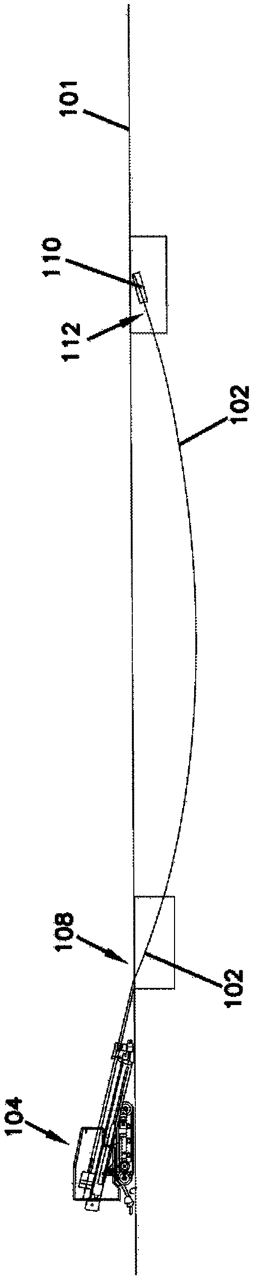
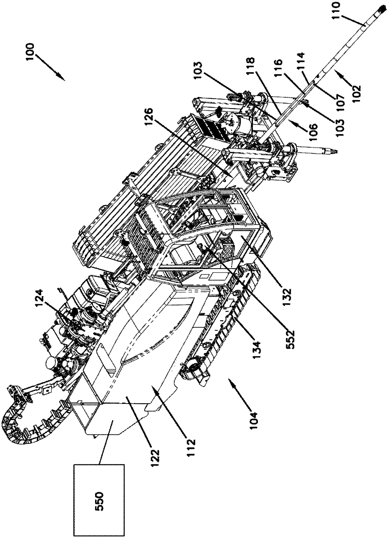
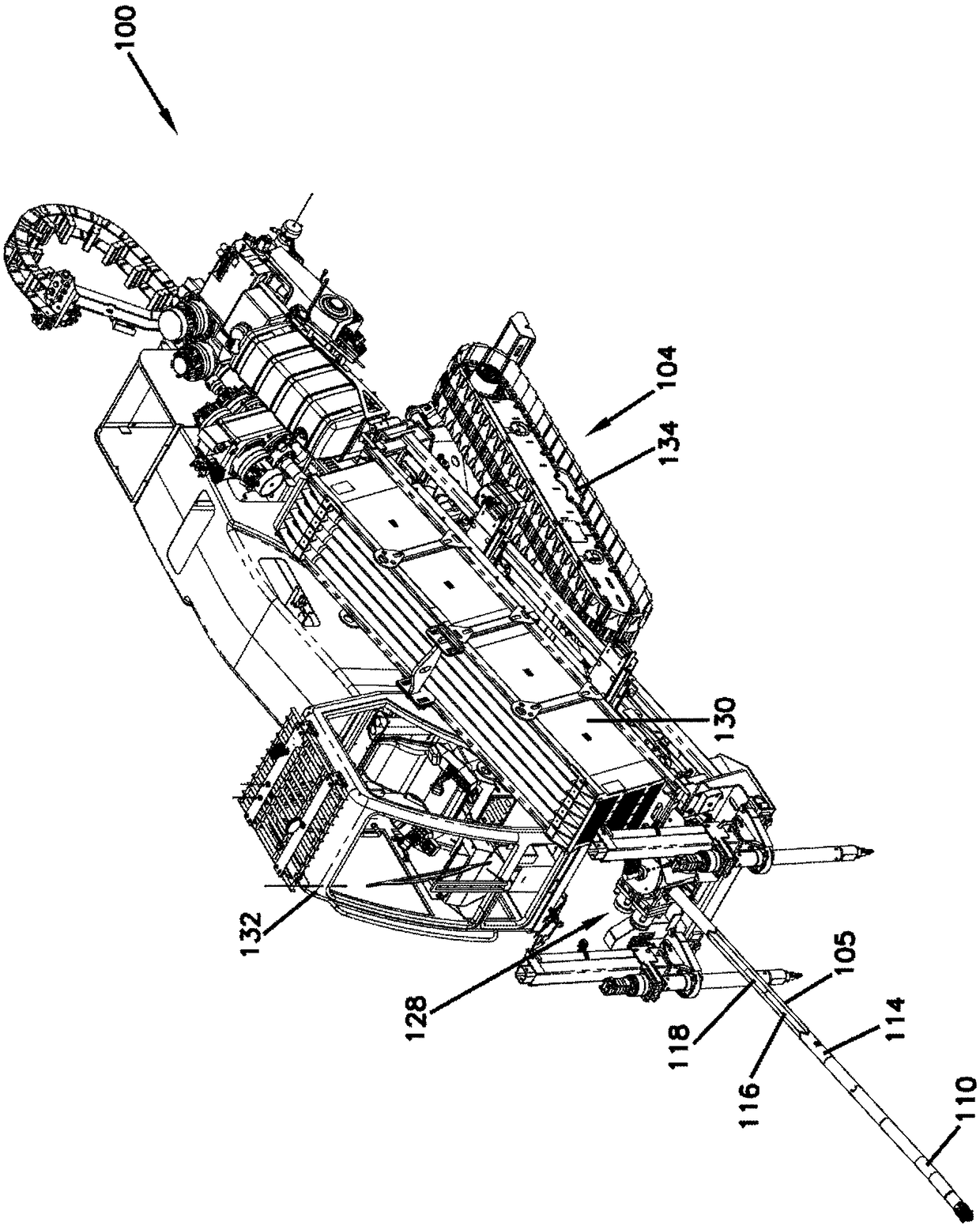
[0104] Figure 1-3 A twin rod drilling system 100 is shown. The twin rod drilling system 100 includes a drill string 102 that is guided into the surface 101 by a drilling machine 104 . Example drill string 102 at figure 1 shown in .

[0105] The drilling machine 104 includes a prime mover 122 (eg, a diesel engine), a gearbox 124, a rack 126, and a disconnect mechanism 128 (eg, a vise system). Optionally, drilling machine 104 may include a drill rod storage bin 130 , an operator station 132 and a set of tracks or wheels 134 .

[0106] Dri...


PUM


Abstract

A drilling system includes a hollow outer rod drive shaft that is configured to rotate an outer rod of a drill string. The outer rod drive shaft is driven by an offset hydraulic drive system. The drilling system also includes a hollow inner rod drive shaft that is configured to couple to and rotate an inner rod of the drill string at a first end. The inner rod drive shaft is driven by an inline hydraulic drive system. The inner rod drive shaft further defines an axial fluid flow passage. The drilling system also includes a fluid inlet passage that is axially aligned with the axial fluid flow passage of the inner rod drive shaft. The fluid inlet passage is operatively connected to a second end of the inner rod drive shaft. The fluid inlet passage is configured to direct fluid into the axialfluid flow passage of the inner rod drive shaft. The outer rod drive shaft and the inner rod drive shaft are mounted in fixed relative positions.

Description

[0001] Cross References to Related Applications [0002] This application calls for 62 / 492,818, filed May 1, 2017; 62 / 530,610, filed July 10, 2017; 62 / 530,616, filed July 10, 2017; July 2017 62 / 530,642, filed October 10; 62 / 566,971, filed October 2, 2017; and U.S. Provisional Patent Application No. 62 / 567,624, filed October 3, 2017, in their entirety Incorporated herein by reference. Background technique [0003] Twin-pipe ("twin-rod") drilling systems are known for directional drilling having inner and outer rods. A typical twin-pipe drilling system is generally configured to drive a series of drill pipe end-to-end into the ground to form a drill string. At the end of the drill string is a rotating drilling tool or bit. Twin rod drilling systems typically include a first drive mechanism that controls rotation of the drill bit and a second drive mechanism that controls rotation of the steering element. When drilling a straight well with a twin rod drilling system, the firs...

Claims


Application Information

Patent Timeline
Patent Type & Authority Applications(China)
IPC IPC(8): E21B7/04E21B12/00E21B17/00F16H57/02
CPCE21B7/046E21B17/046E21B17/18E21B7/06E21B3/02E21B7/062E21B7/02E21B17/07E21B19/16
Inventor 坦纳·沃斯克林特·雷克
Owner VERMEER MFG CO
Why Eureka
Try Eureka