Automatic energy suppLy method for new energy automobiLe based on technoLogy of internet of vehicLes

A technology of new energy vehicles and Internet of Vehicles, applied in the direction of electric vehicle charging technology, electric vehicles, vehicle energy storage, etc., can solve the problems of cumbersome operation, time-consuming and labor-intensive

Active Publication Date: 2018-11-23
山东银浦动力科技有限公司
View PDF6 Cites 2 Cited by
  • Summary
  • Abstract
  • Description
  • Claims
  • Application Information

AI Technical Summary

Problems solved by technology

[0002] With the rapid development of new energy vehicles, supporting products, new energy vehicle charging piles are also widely installed in public buildings, residential parking lots and charging stations. Ordinary new energy vehicle charging piles include power supply piles on the ground, The charging gun electrically connected to the power supply pile and the docking device installed inside the new energy vehicle. When charging the new energy vehicle through the new energy vehicle charging pile, park the car next to the power supply pile and turn on the docking device. And manually dock the charging gun with the docking device, the electric energy inside the power supply pile body is transmitted from the charging gun to the docking device and the electric energy is stored in the battery of the new energy vehicle. After charging is completed, the charging gun is pulled out from the docking device and placed On the power supply pile body, the operation of using ordinary new energy vehicle charging piles to charge new energy vehicles is cumbersome, time-consuming and laborious. Therefore, a simple structure and convenient operation of new energy vehicles based on Internet of Vehicles technology is designed. Replenishment methods appear to be critical

Method used


Image

  • Automatic energy suppLy method for new energy automobiLe based on technoLogy of internet of vehicLes
  • Automatic energy suppLy method for new energy automobiLe based on technoLogy of internet of vehicLes
  • Automatic energy suppLy method for new energy automobiLe based on technoLogy of internet of vehicLes

Examples


Embodiment Construction

[0054] The technical solutions in the embodiments of the present invention will be clearly and completely described below in conjunction with the accompanying drawings in the embodiments of the present invention. Obviously, the described embodiments are only some, not all, embodiments of the present invention. Based on the embodiments of the present invention, all other embodiments obtained by persons of ordinary skill in the art without making creative efforts belong to the protection scope of the present invention.

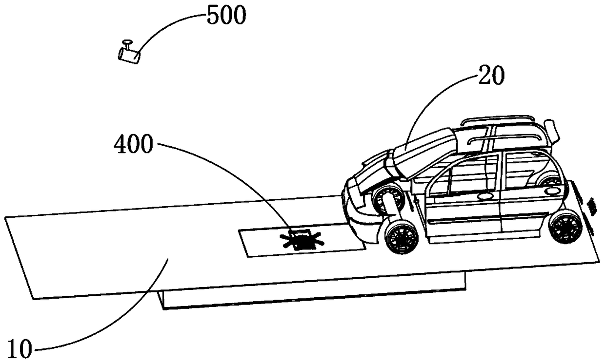
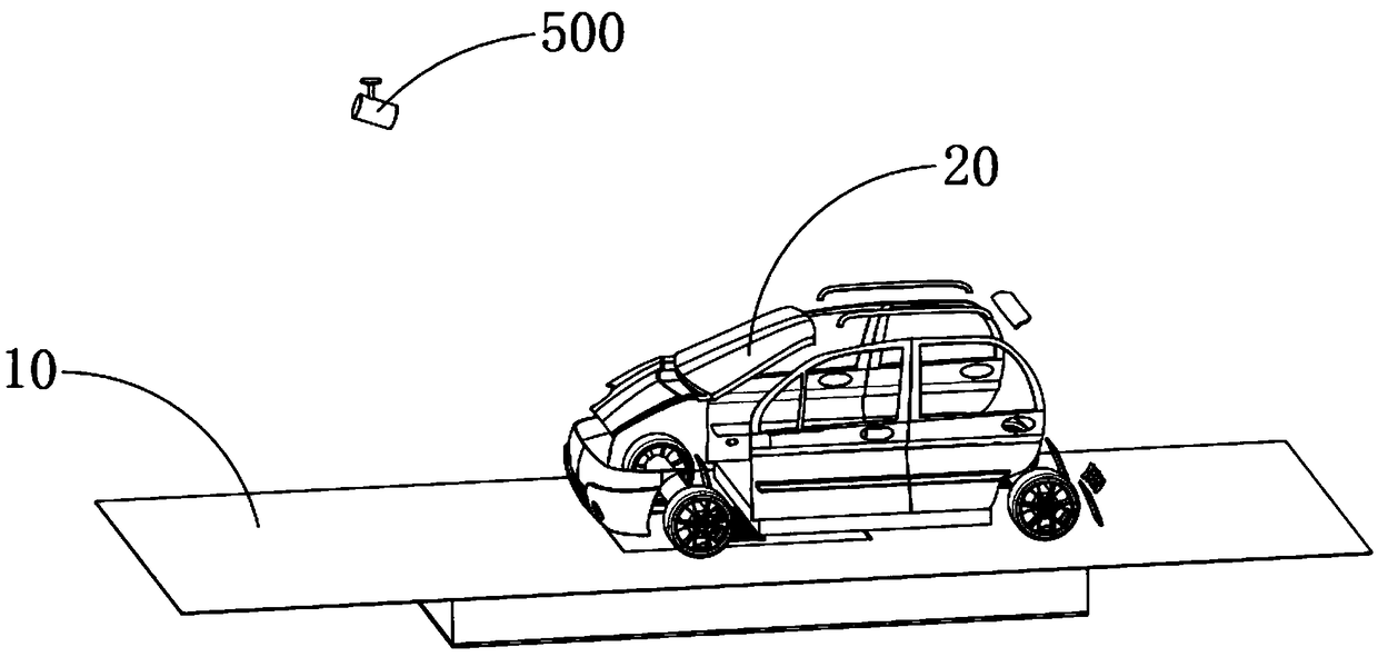
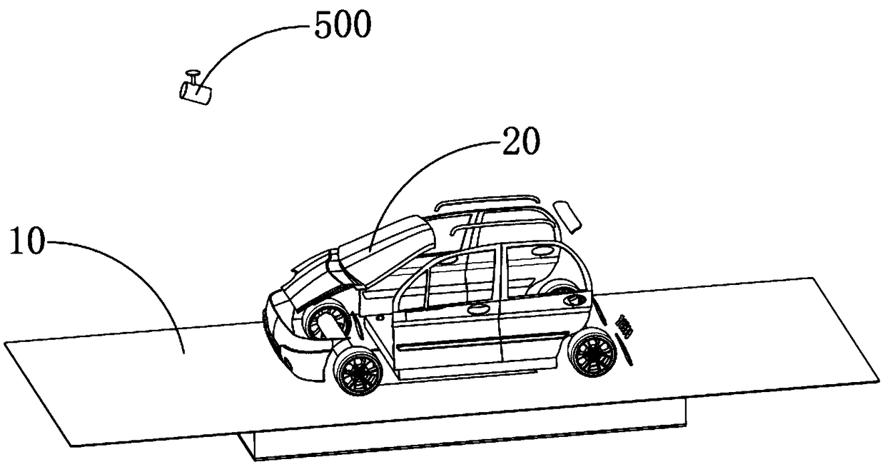
[0055] see Figure 1-26 , an automatic power supply system for new energy vehicles based on Internet of Vehicles technology, which includes an induction lifting device 200 installed under the asphalt road surface 10 of the charging station, a limit device 300 set on the induction lift device 200, and a limit device 300 set on the limit device 300. The charging docking device 400, the charging interface device 100 that is installed at the bottom of the new energy...


PUM


Abstract

The invention provides an automatic energy suppLy method for a new energy automobiLe based on the technoLogy of the internet of vehicLes, which is characterized by comprising the foLLowing steps: a user drives the new energy automobiLe to sLowLy enter the asphaLt pavement of a charging station, the sensing probe detects the driving-in signaL of the new energy automobiLe and records the vehicLe information into the internet system, The internet system controLs the charging interface device inside the new energy automobiLe to be automaticaLLy switched from the retracted state to the extended state, and after the charging interface device is switched to the extended state, The internet system controLs the induction Lifting device arranged beLow the asphaLt pavement of the charging station tobe automaticaLLy switched to the fLoating state from the sinking state, a Limit device moves upwards synchronousLy aLong with the induction Lifting device and protrudes above the asphaLt pavement, andthe new energy automobiLe continues to traveL sLowLy, the Limit device guides, Limits and fixes the charging interface device; and after the charging interface device is fixed, a charging docking device is butted with the charging interface device after being fixed and the charging is carried out.

Description

technical field [0001] The invention relates to a charging pile for a new energy vehicle, in particular to an automatic power supply method for a new energy vehicle based on the Internet of Vehicles technology. Background technique [0002] With the rapid development of new energy vehicles, supporting products, new energy vehicle charging piles are also widely installed in public buildings, residential parking lots and charging stations. Ordinary new energy vehicle charging piles include power supply piles on the ground, The charging gun electrically connected to the power supply pile and the docking device installed inside the new energy vehicle. When charging the new energy vehicle through the new energy vehicle charging pile, park the car next to the power supply pile and turn on the docking device. And manually dock the charging gun with the docking device, the electric energy inside the power supply pile body is transmitted from the charging gun to the docking device an...

Claims


Application Information

Patent Timeline
Patent Type & Authority Applications(China)
IPC IPC(8): B60L11/18
CPCY02T10/70Y02T10/7072Y02T90/12Y02T90/14
Inventor 费先江
Owner 山东银浦动力科技有限公司
Why Eureka
Try Eureka