Telescopic rotary joint

A technology of rotary joints and rotors, applied in mining equipment, earthwork drilling, tunnels, etc., to reduce the risk of wear and improve geological adaptability and safety

Active Publication Date: 2018-11-27
CHINA RAILWAY ENGINEERING EQUIPMENT GROUP CO LTD
View PDF9 Cites 2 Cited by
  • Summary
  • Abstract
  • Description
  • Claims
  • Application Information

AI Technical Summary

Problems solved by technology

At present, there is no device in China about how to solve the problem of how to realize the active expansion and contraction of the passive stirring rod in the excavation chamber of the shield machine

Method used


Image

  • Telescopic rotary joint
  • Telescopic rotary joint

Examples


Embodiment 1

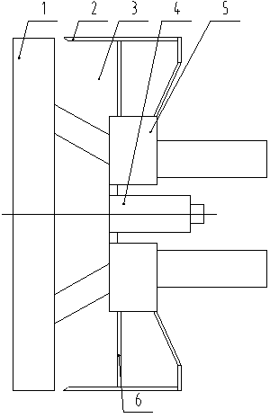
[0020] Embodiment 1: as Figure 1-2 As shown, a telescopic rotary joint includes a cutter head 1, a shield shell 2, an excavation chamber 3, a rotary joint 4, a driving device 5 and a front shield partition 6, and the shield shell 2 is fixed with a front shield partition 6. The drive device 5 is fixed on the front shield partition 6, the middle part of the shield shell 2 is provided with a rotary joint 4, the front end of the shield shell 2 is provided with a cutter head 1, the cutter head 1 is connected with the drive device 5, and the front shield partition 6 is connected with the drive device 5. An excavation chamber 3 is arranged between the cutterheads 1, and the driving device 5 drives the cutterhead 1 to rotate to excavate and cut the stratum, and the muck flows inside the excavation chamber 3.

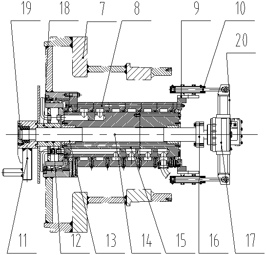
[0021] The rotary joint 4 includes a rotary joint rotor 15 and a rotary joint stator 8, the rotary joint rotor 15 is movably connected with the rotary joint stator 8, a copper ...

Embodiment 2

[0024] Embodiment 2: A telescopic rotary joint, the front end of the stirring shaft 14 is horizontally fixedly connected with the stirring rod 11 through a spline, and the front end of the stirring shaft 14 is clamped and fixed by a semicircular key to prevent the axial movement of the stirring shaft 14, and then use End cover 19 fixedly covers stirring shaft 14, prevents stirring shaft 14 from wearing and tearing in excavation bin 3. All the other are identical with embodiment 1.

Embodiment 3

[0025] Embodiment 3: A telescopic rotary joint, the working method is:

[0026] 1) Telescopic: the hydraulic cylinder 10 stretches back and forth, drives the motor 17 to move back and forth relative to the rotary joint 4, the motor 17 drives the stirring shaft 14 to move back and forth through the coupling 16, and the stirring shaft 14 further drives the stirring rod 11 to stretch;

[0027] 2) Sealing: During the forward and backward movement of the stirring rod 11, the inner seal 12 of the cutter head drive shaft sleeve 18 separates the excavation chamber 3 from the copper sleeve 13, preventing the rotation of the stirring shaft 14 from being obstructed by dregs;

[0028] 3) Adding the improvement liquid: the cutter head drive bushing 18 is fixed to the rotary joint rotor 15, the driving device 5 drives the cutter head 1 to rotate, the rotation of the cutter head 1 drives the rotary joint rotor 15 to rotate, and then introduces the improvement liquid into the cutter head 1. A...


PUM


Abstract

The invention provides a telescopic rotary joint. The joint comprises a cutter plate, a shield housing, an excavating chamber, a rotary joint, a driving device and a front shield separating plate, therotary joint comprises a rotary joint rotor and a rotary joint stator, a copper sleeve is fixed to the rotary joint rotor, one end of a stirring shaft penetrates through the copper sleeve to be fixedly connected with a stirring bar, the other end of the stirring shaft is fixedly connected with a motor through a coupler, the rotary joint stator is fixedly provided with the driving device, the driving device is fixedly provided with a rotary joint fixing frame, the rotary joint fixing frame is fixedly provided with a hydraulic oil cylinder, the hydraulic oil cylinder is fixedly connected with amotor installing frame, and the motor is fixed to the interior of the motor installing frame. The length of the stirring bar is adjustable, adjustment can be conducted according to different geologies to reduce the risks of stirring damage and the wearing of the sealing pressing ring of the driving device, and the geological adaptability and safety of a shield machine are improved.

Description

technical field [0001] The invention relates to the technical field of excavation and construction of a tunnel shield machine, in particular to a telescopic rotary joint. Background technique [0002] At present, in the shield construction of existing underground tunnel projects in China, due to the complex and diverse geology, there are various types of shield machines, and the earth pressure balance shield machine is one of them. During the excavation process of the earth pressure balance shield machine, after the muck modifier is fully stirred in the excavation chamber to form flow-plastic muck, it forms a pressure balance with the face of the tunnel to keep the ground when the shield is excavating. stability. [0003] However, in traditional design shields, there is a passive stirring rod on the partition of the main driving device, and its extension length cannot be adjusted. The passive stirring rod on the top is easy to be knocked off, and the falling passive stirri...

Claims


Application Information

Patent Timeline
Patent Type & Authority Applications(China)
IPC IPC(8): E21D9/06E21D9/08E21D9/00
CPCE21D9/001E21D9/0642E21D9/0678E21D9/08
Inventor 高文梁董亚岭王昆廖兆锦马钢建许发成
Owner CHINA RAILWAY ENGINEERING EQUIPMENT GROUP CO LTD
Why Eureka
Try Eureka