A retractable swivel joint
A technology of rotary joints and rotors, applied in mining equipment, tunnels, earth-moving drilling, etc., to achieve the effect of improving geological adaptability and safety, and reducing the risk of wear and tear
- Summary
- Abstract
- Description
- Claims
- Application Information
AI Technical Summary
Problems solved by technology
Method used
Image
Examples
Embodiment 1
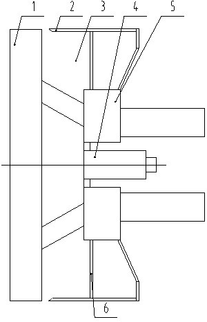
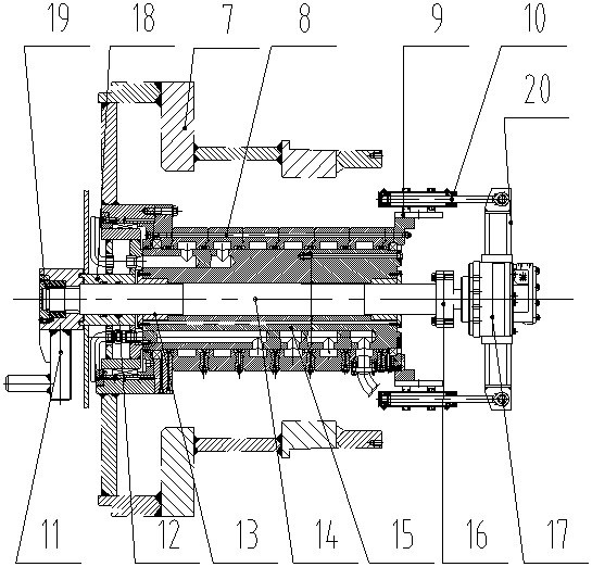
[0020] Example 1: as Figure 1-2 As shown, a retractable rotary joint includes a cutter head 1, a shield shell 2, an excavation bin 3, a rotary joint 4, a driving device 5 and a front shield partition 6, and the front shield partition is fixed on the shield shell 2. 6. A drive device 5 is fixed on the front shield clapboard 6, a rotary joint 4 is arranged in the middle of the shield shell 2, a cutter head 1 is arranged at the front end of the shield shell 2, the cutter head 1 is connected with the driving device 5, and the front shield clapboard 6 is connected with the driving device 5. An excavation bin 3 is arranged between the cutter heads 1 , the driving device 5 drives the cutter head 1 to rotate to excavate and cut the stratum, and the slag flows inside the excavation bin 3 .
[0021] The rotary joint 4 includes a rotary joint rotor 15 and a rotary joint stator 8. The rotary joint rotor 15 is movably connected to the rotary joint stator 8. A copper sleeve 13 is fixed on ...
Embodiment 2
[0024] Embodiment 2: A telescopic rotary joint, the front end of the stirring shaft 14 is horizontally and fixedly connected to the stirring rod 11 through splines, and the front end of the stirring shaft 14 is clamped and fixed by a semicircular key to prevent the stirring shaft 14 from moving axially, and then use The end cover 19 is fixed to cover the stirring shaft 14 to prevent the stirring shaft 14 from being worn in the excavation bin 3 . The rest are the same as in Example 1.
Embodiment 3
[0025] Embodiment 3: a retractable rotary joint, the working method is:
[0026] 1) Telescopic: The hydraulic cylinder 10 is telescopic forward and backward, which drives the motor 17 to move forward and backward relative to the rotary joint 4. The motor 17 drives the stirring shaft 14 to move forward and backward through the coupling 16, and the stirring shaft 14 further drives the stirring rod 11 to expand and contract;
[0027] 2) Sealing: During the forward and backward movement of the stirring rod 11, the inner seal 12 of the cutter head drive shaft sleeve 18 separates the excavation bin 3 from the copper sleeve 13, so as to prevent the dregs from hindering the rotation of the stirring shaft 14;
[0028] 3) Adding the improvement liquid: The cutter head drive bushing 18 is fixed with the rotary joint rotor 15, the driving device 5 drives the cutter head 1 to rotate, and the cutter head 1 rotates to drive the rotary joint rotor 15 to rotate, and then the improvement liquid ...
PUM
 Abstract
Description
Claims
Application Information
 - R&D
- Intellectual Property
- Life Sciences
- Materials
- Tech Scout
- Unparalleled Data Quality
- Higher Quality Content
- 60% Fewer Hallucinations
Browse by: Latest US Patents, China's latest patents, Technical Efficacy Thesaurus, Application Domain, Technology Topic, Popular Technical Reports.
© 2025 PatSnap. All rights reserved.Legal|Privacy policy|Modern Slavery Act Transparency Statement|Sitemap|About US| Contact US: help@patsnap.com


