Cross polarization error correction method for microwave radiometer

A microwave radiometer and error correction technology, applied in the field of microwave remote sensing, can solve problems such as difficult to obtain, difficult to guarantee calculation accuracy, and complicated Faraday rotation angle calculation, so as to improve the efficiency of error correction and avoid complex processes.

Inactive Publication Date: 2018-11-30
XIAN INSTITUE OF SPACE RADIO TECH
View PDF6 Cites 6 Cited by
  • Summary
  • Abstract
  • Description
  • Claims
  • Application Information

AI Technical Summary

Problems solved by technology

[0022] At present, for cross-polarization errors, each cross-polarization error is corrected one by one in the order of antenna cross-polarization correction, polarization rotation correction, and Faraday rotation correction, but such correction methods have great limitations: ( 1) For the antenna cross-polarization correction, it is necessary to accurately measure the antenna pattern within the range of 4pi. The current technical level is difficult to achieve, and it is difficult to obtain an accurate cross-polarization correction matrix F n , at the same time, after the satellite is in orbit, the antenna radiation characteristics may change, which may cause the ground test antenna pattern to be no longer applicable; (2) The third component of the full polarization brightness temperature vector T B3 It is extremely sensitive to polarization rotation and Faraday rotation. For polarization rotation correction, it is necessary to accurately measure antenna installation deviation, satellite attitude, antenna scanning azimuth angle, pitch angle, etc. There are many parameters involved, and it is difficult to guarantee the measurement accuracy of each item. , at the same time, the calculation of the Faraday rotation angle is more complicated, and the calculation accuracy is difficult to guarantee; (3) The method of correcting each error source one by one can only correct these three errors. The error cannot be corrected

Method used


Image

  • Cross polarization error correction method for microwave radiometer
  • Cross polarization error correction method for microwave radiometer
  • Cross polarization error correction method for microwave radiometer

Examples


specific Embodiment approach

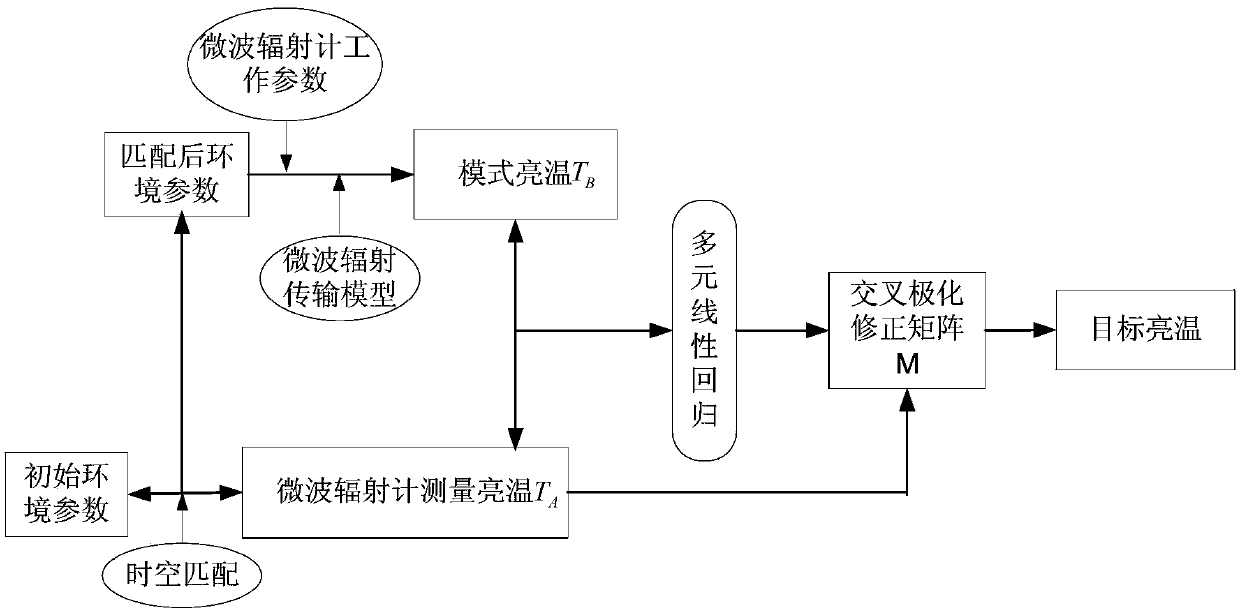
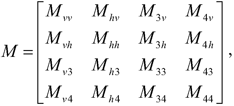
[0047] figure 1 Shown is the flow chart of the method of the present invention, which mainly includes the following parts: one is to match the environmental parameters with the brightness temperature measured by the microwave radiometer in time and space; the other is to calculate the mode brightness temperature according to the radiation transfer model; the third is to calculate the brightness temperature according to the multiple linear regression algorithm A cross-polarization correction matrix; finally, cross-polarization error correction can be implemented according to the cross-polarization matrix. The specific implementation is as follows:

[0048] (1) Acquisition of environmental parameters

[0049] In order to calculate the brightness temperature of the model, it is necessary to obtain various environmental parameters such as sea surface temperature, sea water salinity, wind speed and relative wind direction, atmospheric water vapor content, and cloud water content. ...


PUM


Abstract

The invention discloses a cross polarization error correction method for a microwave radiometer. The defects of more correction steps, large calculated amount and heavy dependence on ground test parameters in an existing cross polarization error correction method for the microwave radiometer are solved. A new correction method is provided, based on the calibration of measured values of the microwave radiometer and the correction of the cold air overflow, multiple linear regression of the mode bright temperature data and the measured bright temperature of the microwave radiometer is carried outto directly obtain a correction matrix for all the cross polarization effects, and the cross polarization error correction of the measured bright temperature is realized. Compared with the existing cross polarization error correction method, the cross polarization error correction method has the advantages that correction can be completed without obtaining antenna pattern data, antenna installation deviation, satellite attitude and other parameters, and cross polarization errors from different sources can be uniformly corrected to improve the accuracy and speed of data processing.

Description

technical field [0001] The invention relates to a method for correcting cross-polarization errors of a microwave radiometer, belonging to the technical field of microwave remote sensing. Background technique [0002] When the microwave radiometer observes the ground object, the energy of the ground object is passively received through the antenna. Due to the characteristics of the parabolic antenna itself, such as reflectivity loss, end-to-port isolation, and cross-polarization characteristics of the reflecting surface, the antenna is not scheduled. At the same time, the target scene does not match the antenna boresight polarization reference, and the Faraday rotation is also the cause of the cross-polarization error. It can be seen that the sources of antenna cross-polarization errors are complex, and it is difficult to establish a cross-polarization transmission equation that includes all error sources. It can only be corrected for different cross-polarization error source...

Claims


Application Information

Patent Timeline
Patent Type & Authority Applications(China)
IPC IPC(8): G01R35/00
CPCG01R35/005
Inventor 邢妍王丛丛金旭李一楠李浩吕容川王佳坤沈尚宇
Owner XIAN INSTITUE OF SPACE RADIO TECH
Why Eureka
Try Eureka