
A mobile road barricade

A mobile, barricade technology, applied in the directions of roads, roads, road signs, etc., can solve the problem that vehicles cannot function as effective restrictions

Inactive Publication Date: 2018-12-07
四川东拓建设工程有限公司
View PDF0 Cites 0 Cited by
  • Summary
  • Abstract
  • Description
  • Claims
  • Application Information

AI Technical Summary

Problems solved by technology

At present, most of the existing road barriers are guardrail structures or cone-shaped plastic products. These road barriers generally only serve as a warning function, and cannot effectively limit the malicious collision of vehicles.

Method used


Image

  • A mobile road barricade

Examples


Embodiment Construction

[0011] The present invention will be further described below in conjunction with the accompanying drawings and specific embodiments.

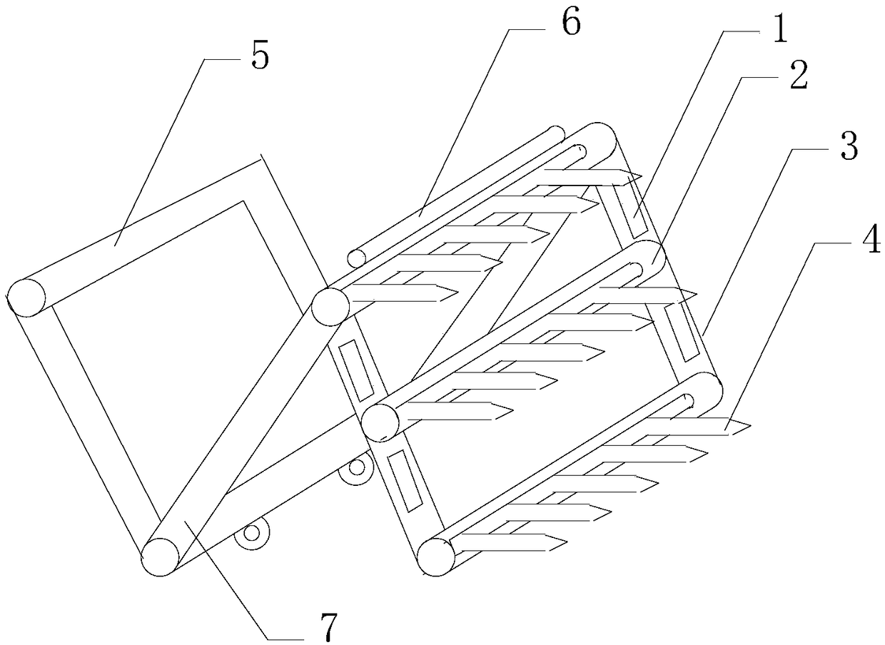
[0012] Such as figure 1 A kind of mobile road barricade shown, comprises barricade body, and described barricade body is N font, and described barricade body comprises barricade unit 3 and support 7, and described barricade unit 3 is frame shape, and the barricade unit 3 The middle part is provided with a crossbar 2, and the crossbar 2 is provided with a barb 4, and the upper end of the roadblock unit 3 is hingedly connected with the bracket 7, and the roadblock unit 3 and the bracket 7 form an inverted V-shaped structure, and the bracket 7 is provided with push handle 5, and the bottom of described support 7 is provided with roller.

[0013] Preferably, barbs 4 are provided on both the top and the bottom of the barrier unit 3 .

[0014] Preferably, the barrier unit 3 is provided with a reflective strip 1 .

[0015] Preferably, the barrier u...


PUM


Abstract

A mobile road barricade is disclosed, including roadblocks, the roadblock is N-shaped, the roadblock comprises a roadblock unit and a bracket, The roadblock unit is in the shape of a frame, a cross bar is arranged in the middle of the roadblock unit, barbs are arranged on the cross bar, the upper end of the roadblock unit is hinged with the bracket, the roadblock unit and the bracket form an inverted V-shaped structure, a pusher is arranged on the bracket, and a roller is arranged at the bottom of the bracket. The invention is movable, and barbs on the barricade unit can effectively limit theeffect of the barb on the vehicle airway.

Description

technical field [0001] The invention relates to the field of traffic road barriers, in particular to a mobile road barrier. Background technique [0002] Road barriers refer to obstacles set up on the road, which are widely used in urban traffic, the gates of the military and important state agencies and their surroundings, pedestrian streets, expressways, toll stations, airports, schools, banks, large clubs, parking lots and many other occasions. Through the restrictions on passing vehicles, the traffic order is effectively guaranteed, that is, the safety of major facilities and places. At present, most of the existing road barriers are guardrail structures or conical plastic products. These road barriers generally only play a warning role, and cannot effectively restrict vehicles that maliciously collide. Contents of the invention [0003] The purpose of the present invention is to solve the above problems in the prior art, and provide a mobile road barrier that can eff...

Claims


Application Information

Patent Timeline
IPC IPC(8): E01F13/12E01F9/619
CPCE01F13/12E01F9/619
Inventor 李红
Owner 四川东拓建设工程有限公司
Learn More