Heat exchange equipment

A heat exchange equipment and heat exchanger technology, applied in the field of heat exchange, can solve the problems of glue viscosity being greatly affected by the environment and easy to fail, and achieve the effect of solving the falling off of foam and improving the overall firmness

Inactive Publication Date: 2018-12-07
SANHUA HANGZHOU MICRO CHANNEL HEAT EXCHANGER
View PDF0 Cites 0 Cited by
  • Summary
  • Abstract
  • Description
  • Claims
  • Application Information

AI Technical Summary

Problems solved by technology

[0002] In the related art, the heat exchanger and the foam are fixed to each other mainly by glue, but the viscosity of the glue is greatly affected by the environment and is prone to failure.

Method used


Image

  • Heat exchange equipment
  • Heat exchange equipment
  • Heat exchange equipment

Examples


Embodiment Construction

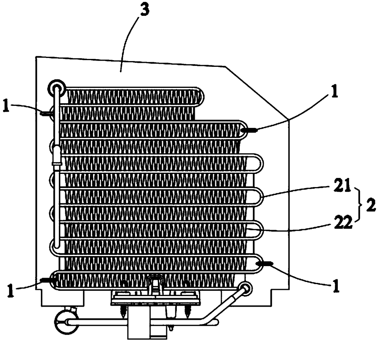
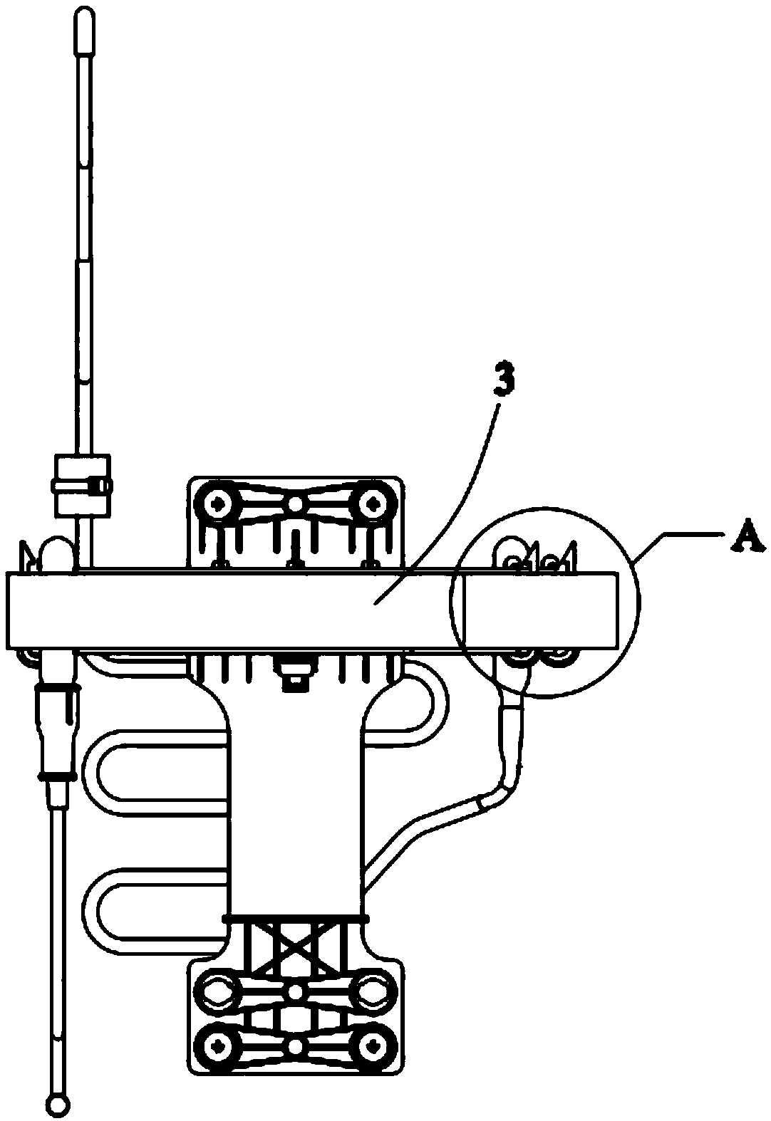
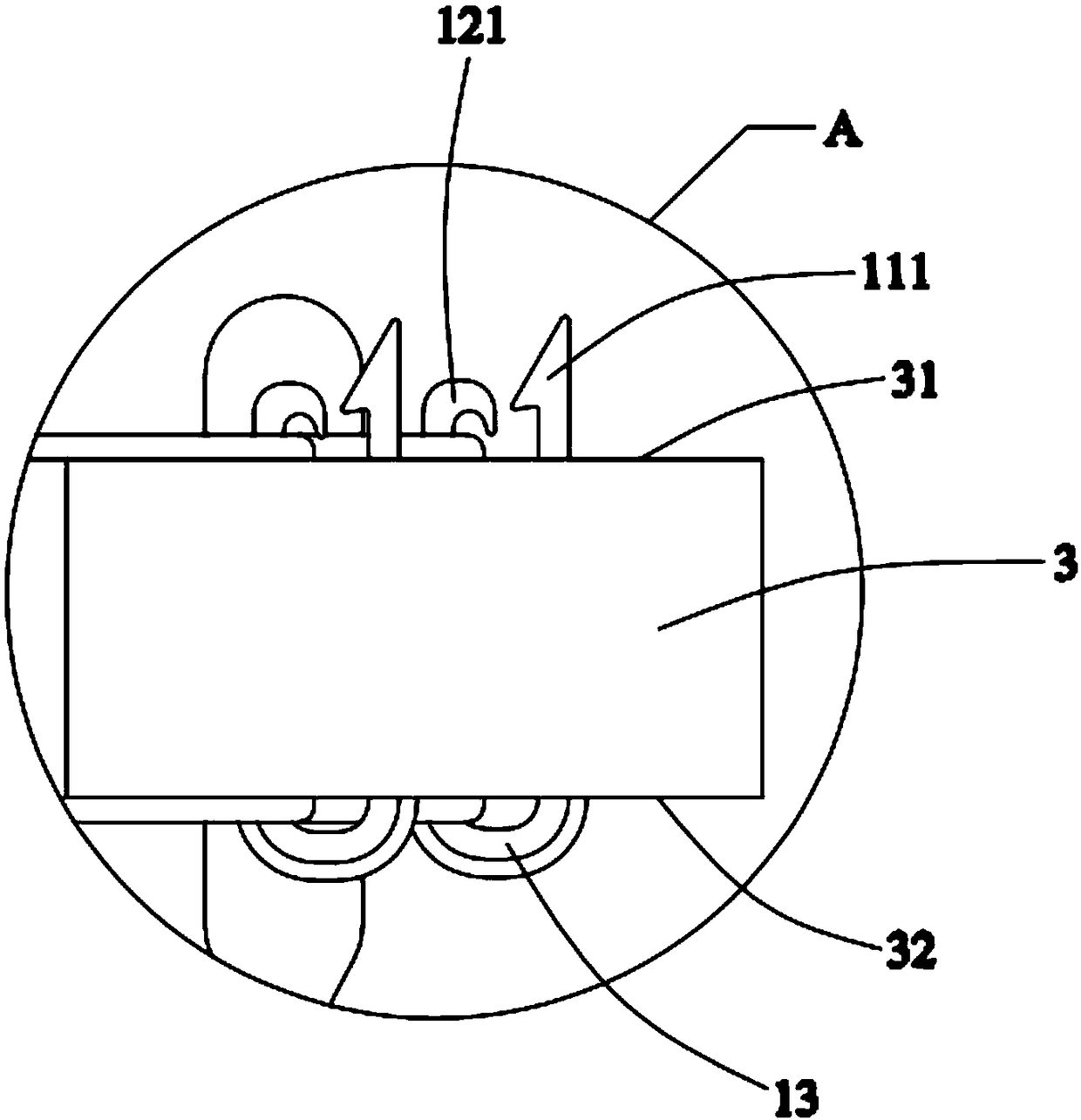
[0023] Embodiments of the present invention are described in detail below, examples of which are shown in the drawings, wherein the same or similar reference numerals designate the same or similar elements or elements having the same or similar functions throughout. The embodiments described below by referring to the figures are exemplary only for explaining the present invention and should not be construed as limiting the present invention.

[0024] In describing the present invention, it should be understood that the terms "center", "longitudinal", "transverse", "length", "width", "thickness", "upper", "lower", "front", " Orientation indicated by rear, left, right, vertical, horizontal, top, bottom, inside, outside, clockwise, counterclockwise, etc. The positional relationship is based on the orientation or positional relationship shown in the drawings, which is only for the convenience of describing the present invention and simplifying the description, rather than indicati...


PUM

PropertyMeasurementUnit
Lengthaaaaaaaaaa

Abstract

The invention provides heat exchange equipment. The heat exchange equipment comprises a heat exchanger and foam, and further comprises a connecting structure, wherein the connecting structure is connected with the heat exchanger and the foam, the connecting structure is provided with an accommodating space, and the connecting structure at least partially penetrates the foam and enables the foam tobe at least partially attached to the heat exchanger. Compared with the related art, the heat exchange equipment has the advantage that the overall firmness is relatively improved.

Description

technical field [0001] The invention relates to the field of heat exchange, in particular to a heat exchange device. Background technique [0002] In the related art, the heat exchanger and the foam are fixed to each other mainly by glue, but the viscosity of the glue is greatly affected by the environment and is prone to failure. Therefore, further improvements can be made. Contents of the invention [0003] The purpose of the present invention is to provide a heat exchange device with better firmness. [0004] In order to achieve the above object, the present invention provides a heat exchange device, including a heat exchanger and foam, the heat exchange device also includes a connection structure, the connection structure connects the heat exchanger and the foam, the The connection structure also has a receiving space, the connection structure at least partially passes through the foam and at least partially attaches the foam to the heat exchanger. [0005] Optional...

Claims


Application Information

Patent Timeline
IPC IPC(8): F28F9/26
CPCF28F9/26
Inventor 崔凯
Owner SANHUA HANGZHOU MICRO CHANNEL HEAT EXCHANGER
Why Eureka
Try Eureka