A small-diameter cylindrical target continuous launching device
A launching device, a cylindrical technology, applied in the direction of the launching device, firing/trigger mechanism, grabbing hook, etc., can solve the problems of continuous launching of small targets that are difficult to manually load, and are not applicable to small targets, etc., and achieve the effect of infinite continuous launch
- Summary
- Abstract
- Description
- Claims
- Application Information
AI Technical Summary
Problems solved by technology
Method used
Image
Examples
specific Embodiment approach 1
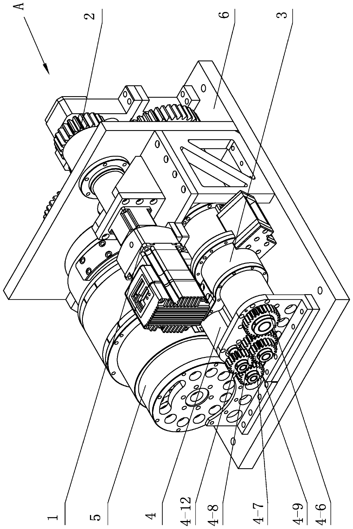
[0036] Specific implementation mode one: combine figure 1 Describe this embodiment, a kind of small-diameter cylindrical target continuous launching device of this embodiment is characterized in that: it comprises drive system 1, pin supply system 3, target shell transfer device 4, launch subsystem 5 and support 6, for The bullet system 3 and the launch subsystem 5 are installed on the bracket 6 respectively, and the pin system 3 is used to separate the target bullet 3-2 from the bullet chain, and the launch subsystem 5 is used to realize the launch of the target bullet 3-2 and the discharge of the empty shell case , the drive system 1 transmits the power to the pin supply system 3 and the launch subsystem 5 respectively and drives the pin supply system and the launch subsystem to work synchronously and cooperatively. The target bullet transfer device 4 is arranged between the pin supply system 3 and the launch subsystem 5, The inlet end of the target bomb transfer device 4 is...
specific Embodiment approach 2
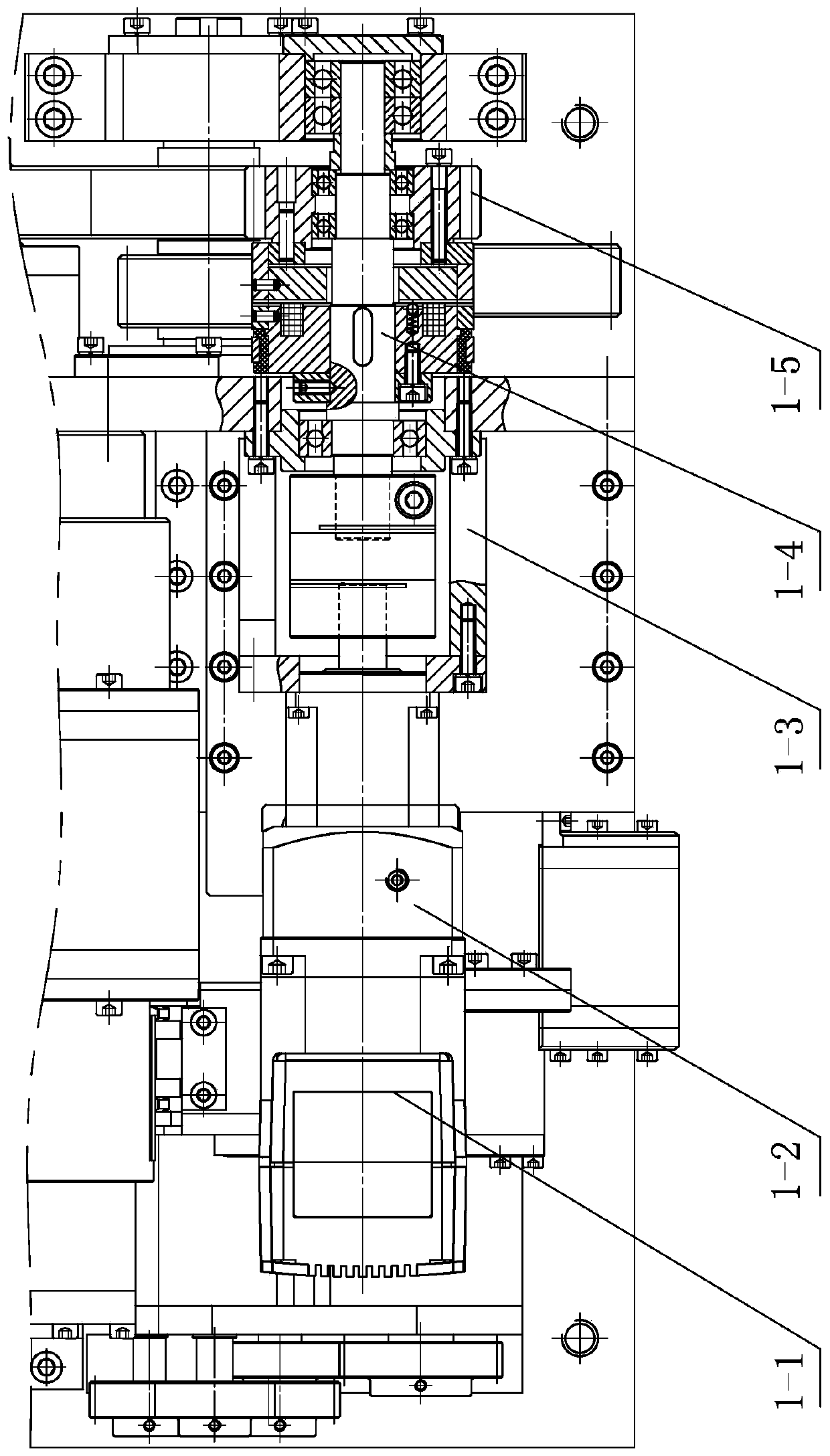
[0037] Specific implementation mode two: combination figure 2 and image 3 Describe this embodiment, the driving system 1 of this embodiment comprises the second motor 1-1, speed reducer 1-2, coupling 1-3, driving system output shaft 1-4, driving system output gear 1-5 and transmission Component 2, the reducer 1-2 is connected to the output end of the second motor 1-1, one end of the drive system output shaft 1-4 is connected to the reducer 1-2 through a coupling 1-3, and the drive system output shaft 1-4 The drive system output gear 1-5 is installed at the other end, and the transmission assembly 2 is located at the output end of the drive system 1,
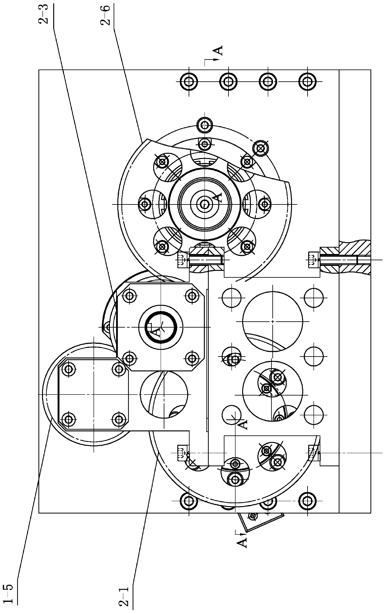
[0038] Transmission assembly 2 comprises input gear 2-1 for pinball system, first transition gear 2-3, transition shaft 2-4, launch subsystem input gear 2-6 and second transition gear 2-7, for pinball system input gear 2 -1 is installed on one end of the pin supply system drive shaft 2-2 of the pin supply system 3, the launch...
specific Embodiment approach 3
[0039] Specific implementation mode three: combination Figure 2 to Figure 4 Describe this embodiment, the drive system 1 of this embodiment includes a controller and two first motors, wherein the output end of one of the first motors is connected with the pin supply system drive shaft 2-2 of the pin supply system 3 and is the pin supply system 3 provides power, the output end of the other first motor is connected with the launch subsystem drive shaft 2-5 of the launch subsystem 5 and provides power for the launch subsystem 5, the controller is installed on the bracket 6, and the controller controls the two first A motor respectively drives the synchronous movement of the pinball supply system drive shaft 2-2 of the pinball system 3 and the launch subsystem drive shaft 2-5 of the launch subsystem 5. In this way, the two first motors directly drive the pin supply system drive shaft 2-2 of the pin supply system 3 and the launch subsystem drive shaft 2-5 of the launch subsystem 5...
PUM
 Abstract
Description
Claims
Application Information
 - R&D
- Intellectual Property
- Life Sciences
- Materials
- Tech Scout
- Unparalleled Data Quality
- Higher Quality Content
- 60% Fewer Hallucinations
Browse by: Latest US Patents, China's latest patents, Technical Efficacy Thesaurus, Application Domain, Technology Topic, Popular Technical Reports.
© 2025 PatSnap. All rights reserved.Legal|Privacy policy|Modern Slavery Act Transparency Statement|Sitemap|About US| Contact US: help@patsnap.com


