
A Coaxial Photoelectric Reconnaissance System

A photoelectric reconnaissance, coaxial technology, applied in the field of reconnaissance systems, can solve the problems of system volume, large weight, lost targets, and later instability of optical axis non-parallelism

Active Publication Date: 2021-07-06
江苏无线电厂有限公司
View PDF4 Cites 0 Cited by
  • Summary
  • Abstract
  • Description
  • Claims
  • Application Information

AI Technical Summary

Problems solved by technology

In China, visible light and infrared optical systems and laser optical systems are usually designed separately and independently, resulting in a large system size and weight. At the same time, the optical axis non-parallelism between the systems requires more complicated calibration and is not stable in the later stage.
In addition, when the external observation environment changes, such as the target is blocked, camouflaged, and smoky, and the optical path and band conversion are performed, the target needs to be searched again. When the observed target moves too fast, the target may be lost
It is difficult to meet future applications with increasingly stringent requirements on size and weight with the current technical approach of simply piecing together various sensors. Therefore, it is of great significance to study miniaturized coaxial photoelectric reconnaissance systems

Method used


Image

  • A Coaxial Photoelectric Reconnaissance System
  • A Coaxial Photoelectric Reconnaissance System
  • A Coaxial Photoelectric Reconnaissance System

Examples


Embodiment Construction

[0029] In order to make the purpose and technical solutions of the embodiments of the present invention more clear, the technical solutions of the embodiments of the present invention will be clearly and completely described below in conjunction with the drawings of the embodiments of the present invention. Apparently, the described embodiments are some, not all, embodiments of the present invention. Based on the described embodiments of the present invention, all other embodiments obtained by persons of ordinary skill in the art without creative efforts shall fall within the protection scope of the present invention.

[0030] Those skilled in the art can understand that, unless otherwise defined, all terms (including technical and scientific terms) used herein have the same meaning as commonly understood by one of ordinary skill in the art to which this invention belongs. It should also be understood that terms such as those defined in commonly used dictionaries should be und...


PUM


Abstract

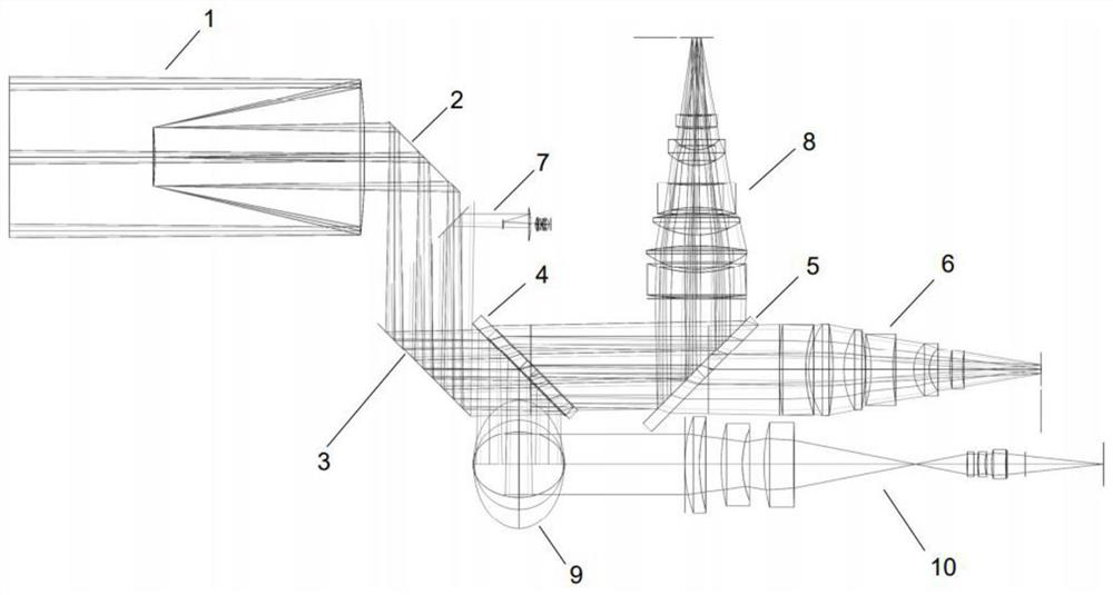
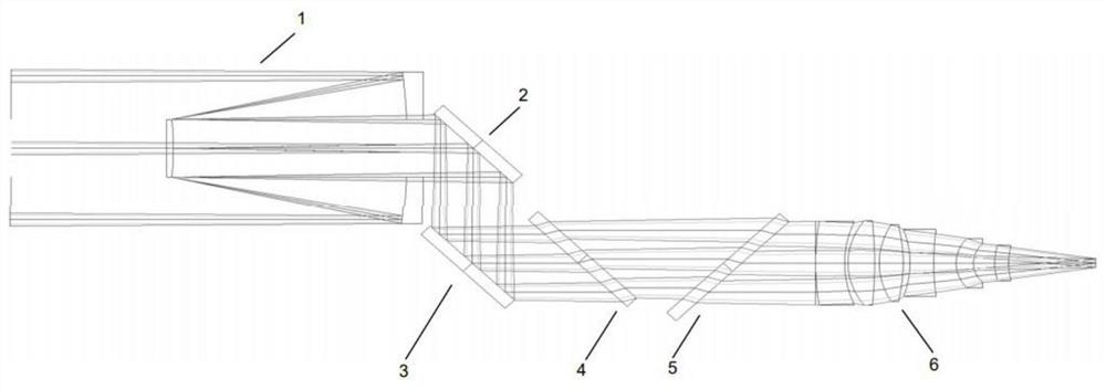
The invention belongs to the field of reconnaissance systems, and in particular relates to a coaxial photoelectric reconnaissance system, which includes a Cassegrain afocal coaxial two-reflector common optical path, an infrared imaging system and a visible light imaging system; the Cassegrain afocal coaxial two-mirror common optical path includes a primary mirror And the secondary mirror, the light emitted by the target is reflected and collimated twice by the primary mirror and the secondary mirror, and then the parallel light is emitted; the Cassegrain afocal coaxial two mirrors and the common optical path are equipped with reflectors on the path of the parallel light output to realize the parallel light. Light refraction; the first mirror is arranged on the reflection light path of the mirror to realize the reflection of infrared light and the transmission of visible light; the visible light imaging system is used to receive and image the visible light transmitted through the first mirror; infrared imaging The system is used for receiving the infrared light reflected by the first mirror and forming an image. It integrates the visible light, infrared band optical system and laser optical system in a small volume to realize the observation of targets in various environments.

Description

technical field [0001] The invention belongs to the field of reconnaissance systems, and in particular relates to a coaxial photoelectric reconnaissance system. Background technique [0002] At present, individual reconnaissance technologies such as long-distance thermal imaging technology, CMOS image sensing technology, and semiconductor laser pumping technology are gradually becoming mature, and integrating multiple sensing technologies to complement each other's advantages can effectively complete day and night battlefield surveillance. , target recognition and instruction, guided fire strikes and other tasks. In China, visible light and infrared band optical systems and laser optical systems are usually designed separately and independently, resulting in a large system size and weight. At the same time, the optical axis non-parallelism between each system requires more complicated calibration and is not stable in the later stage. In addition, when the external observati...

Claims


Application Information

Patent Timeline
Patent Type & Authority Patents(China)
IPC IPC(8): G02B17/06G02B27/10G02B27/14G02B7/182
CPCG02B7/1822G02B17/061G02B27/1006G02B27/141
Inventor 甘欣辉蒋鹏于群宁宋亮姚连喜郭贺李智君万韬蒋晓峰刘鹏顾亮杨苏文崔启胤
Owner 江苏无线电厂有限公司
Learn More