Unlock instant, AI-driven research and patent intelligence for your innovation.
An easy-to-lap cable tray
What is Al technical title?
Al technical title is built by PatSnap Al team. It summarizes the technical point description of the patent document.
A cable tray, a convenient technology, applied in the direction of electrical components, etc., can solve the problems of lack of connection mechanism, lack of convenient installation of protective end caps, cable damage, etc.
Active Publication Date: 2020-08-14
镇江浩宇电气有限公司
View PDF7 Cites 0 Cited by
Summary
Abstract
Description
Claims
Application Information
AI Technical Summary
This helps you quickly interpret patents by identifying the three key elements:
Problems solved by technology
Method used
Benefits of technology
Problems solved by technology
[0003] There are some defects in the currently used cable trays, lack of connecting mechanism, some of the first pipe groove and the second pipe groove are connected by welding, it is inconvenient to replace the first pipe groove and the second pipe groove after damage, and some of the first pipe groove and the second pipe groove are separated Installation will cause a large gap between the first pipe groove and the second pipe groove, which will easily cause insects to enter the inside of the first pipe groove and the second pipe groove, causing damage to the cable. At the same time, it lacks the convenient installation function of the protective end cover. The slider and the chute are installed inside the pipe groove 1 and the pipe groove 2. The protective end cover is inconvenient to slide. After the protective end cover is installed, it is easy to slide due to the external environment
Method used
Image
Click on the blue label to locate the original text in one second.
Reading with bidirectional positioning of images and text.
Examples
Embodiment Construction
[0022] The following will clearly and completely describe the technical solutions in the embodiments of the present invention with reference to the accompanying drawings in the embodiments of the present invention. Obviously, the described embodiments are only some, not all, embodiments of the present invention. Based on the embodiments of the present invention, all other embodiments obtained by persons of ordinary skill in the art without making creative efforts belong to the protection scope of the present invention.
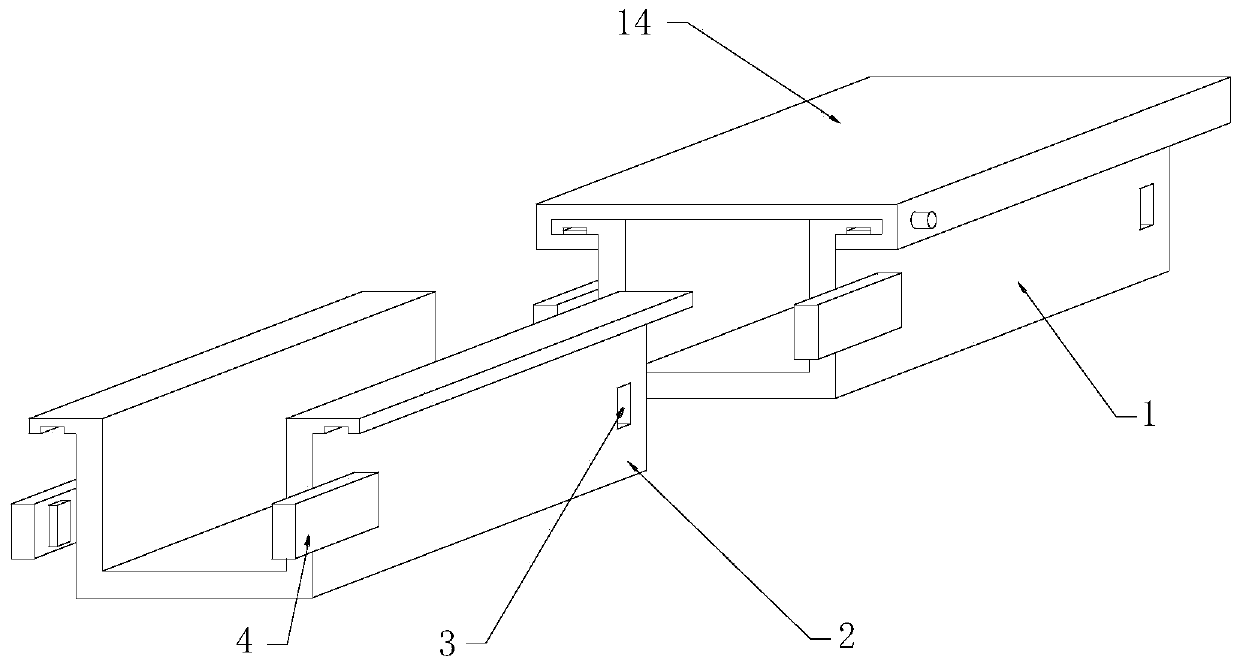
[0023] see Figure 1-5 As shown in the figure, a cable tray that is convenient for lapping includes a pipe groove 1, a pipe groove 2, a limiting square hole 3, a connecting mechanism, and a convenient installation mechanism. One side of the pipe groove 1 is equipped with a pipe groove 2 , The outer surfaces of the pipe groove one 1 and the pipe groove two 2 are provided with limiting square holes 3 .
[0024] The connecting mechanism includes a rotating plate...
PUM
Abstract
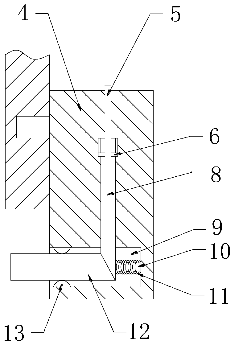
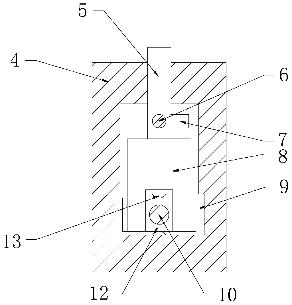
The invention discloses a cable bridge convenient for lapping, comprising a pipe slot 1, a pipe slot 2, a limiting square hole, a rotating plate, a rotating rod, a limiting rod, an L-shaped slot, a push rod, a receiving slot, a guide rod, a spring 1, a clamping plate, a ball 1, a protective end cap, a sliding slot, a ball 2, a pull rod, a spring 2, a limiting block, a limiting hole and a sliding block. The rotating rod is pushed to drive the push rod to move, then the rotating rod is rotated and drives the limiting rod to rotate, the limiting rod is rotatably clamped inside that L-shape grooveto fixing the rotating rod, the push rod moves to squeeze the clamping plate, The clamping plate is squeezed into the limiting square hole, thereby realizing the connection between the pipe groove 1and the pipe groove 2, the sliding block slides in the sliding groove through the ball 2, facilitating the sliding of the protective end cover, and the limiting block is conveniently squeezed into thelimiting hole through the elastic force of the spring 2, thereby realizing the fixing of the protective end cover on the pipe groove 1 and the pipe groove 2.
Description
technical field [0001] The invention relates to a cable bridge, in particular to a cable bridge which is convenient for lapping, and belongs to the technical field of cable bridges. Background technique [0002] Cable trays are divided into trough type, tray type, ladder type, grid type and other structures, and are composed of brackets, supporting arms and installation accessories. The bridge frame in the building can be erected independently or attached to various buildings and pipe gallery supports. It should reflect the characteristics of simple structure, beautiful appearance, flexible configuration and convenient maintenance. All parts need to be galvanized. [0003] There are some defects in the currently used cable trays, lack of connecting mechanism, some of the first pipe groove and the second pipe groove are connected by welding, it is inconvenient to replace the first pipe groove and the second pipe groove after damage, and some of the first pipe groove and the s...
Claims
Application Information
Patent Timeline
Application Date:The date an application was filed.
Publication Date:The date a patent or application was officially published.
First Publication Date:The earliest publication date of a patent with the same application number.
Issue Date:Publication date of the patent grant document.
PCT Entry Date:The Entry date of PCT National Phase.
Estimated Expiry Date:The statutory expiry date of a patent right according to the Patent Law, and it is the longest term of protection that the patent right can achieve without the termination of the patent right due to other reasons(Term extension factor has been taken into account ).
Invalid Date:Actual expiry date is based on effective date or publication date of legal transaction data of invalid patent.

