An optical teaching aid for optical physics experiments

A physical experiment and optical technology, which is applied in the field of optical teaching aids for optical physics experiments, can solve the problems of complex experimental operation and old-fashioned experimental phenomena, and achieve the effect of improving the quality of teaching.

Active Publication Date: 2020-07-17
ANHUI UNIV OF SCI & TECH
View PDF8 Cites 0 Cited by
  • Summary
  • Abstract
  • Description
  • Claims
  • Application Information

AI Technical Summary

Problems solved by technology

[0003] The pinhole imaging experiment is an important link in the experimental learning of junior and senior high school students. However, due to the complexity of the experimental operation and the old-fashioned experimental phenomena, students who understand it can easily understand it, and students who do not understand it will still be unclear. Therefore, how to improve the optical physics experiment The demonstration effect of pinhole imaging and the improvement of teaching quality are issues that many middle and high schools are committed to researching

Method used


Image

  • An optical teaching aid for optical physics experiments
  • An optical teaching aid for optical physics experiments
  • An optical teaching aid for optical physics experiments

Examples


Embodiment Construction

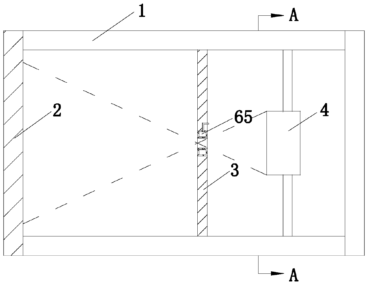
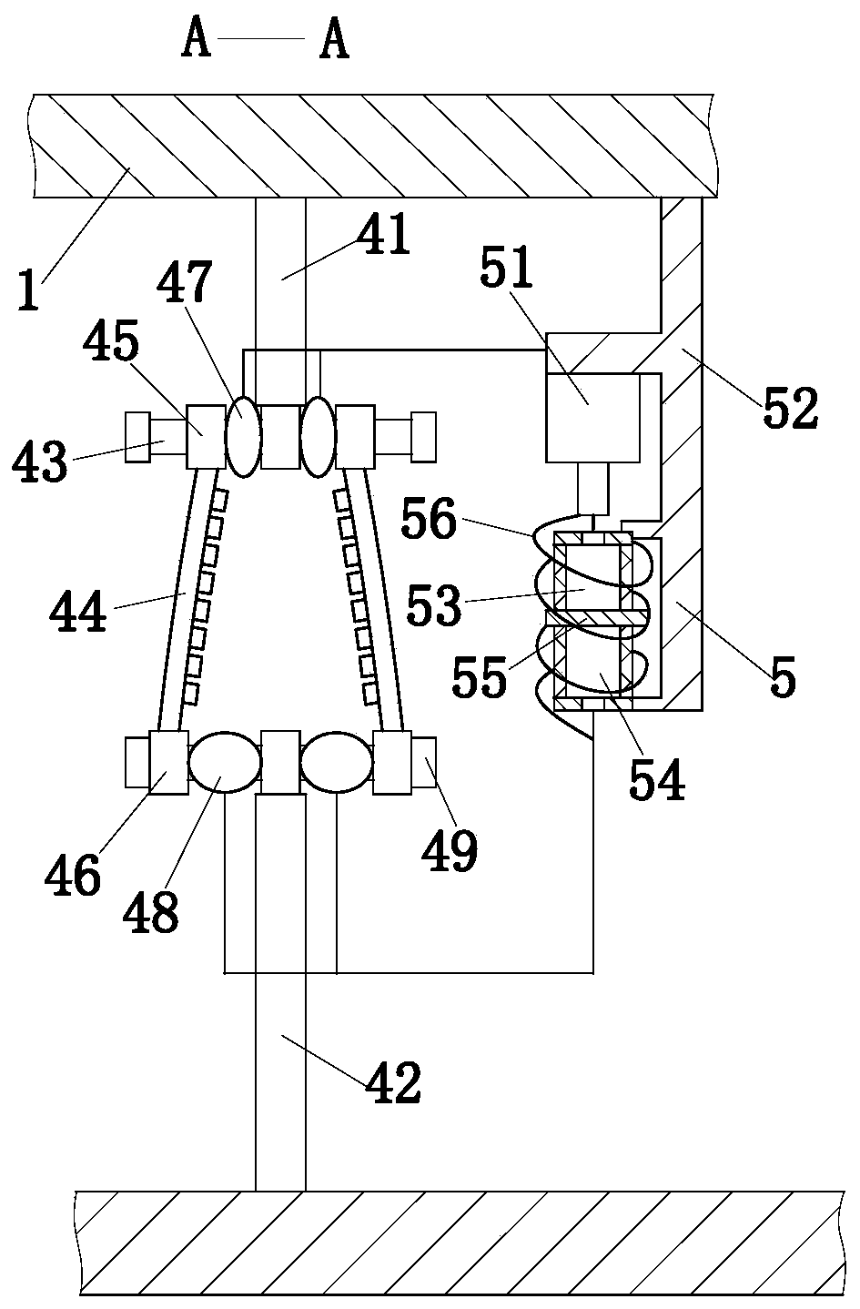
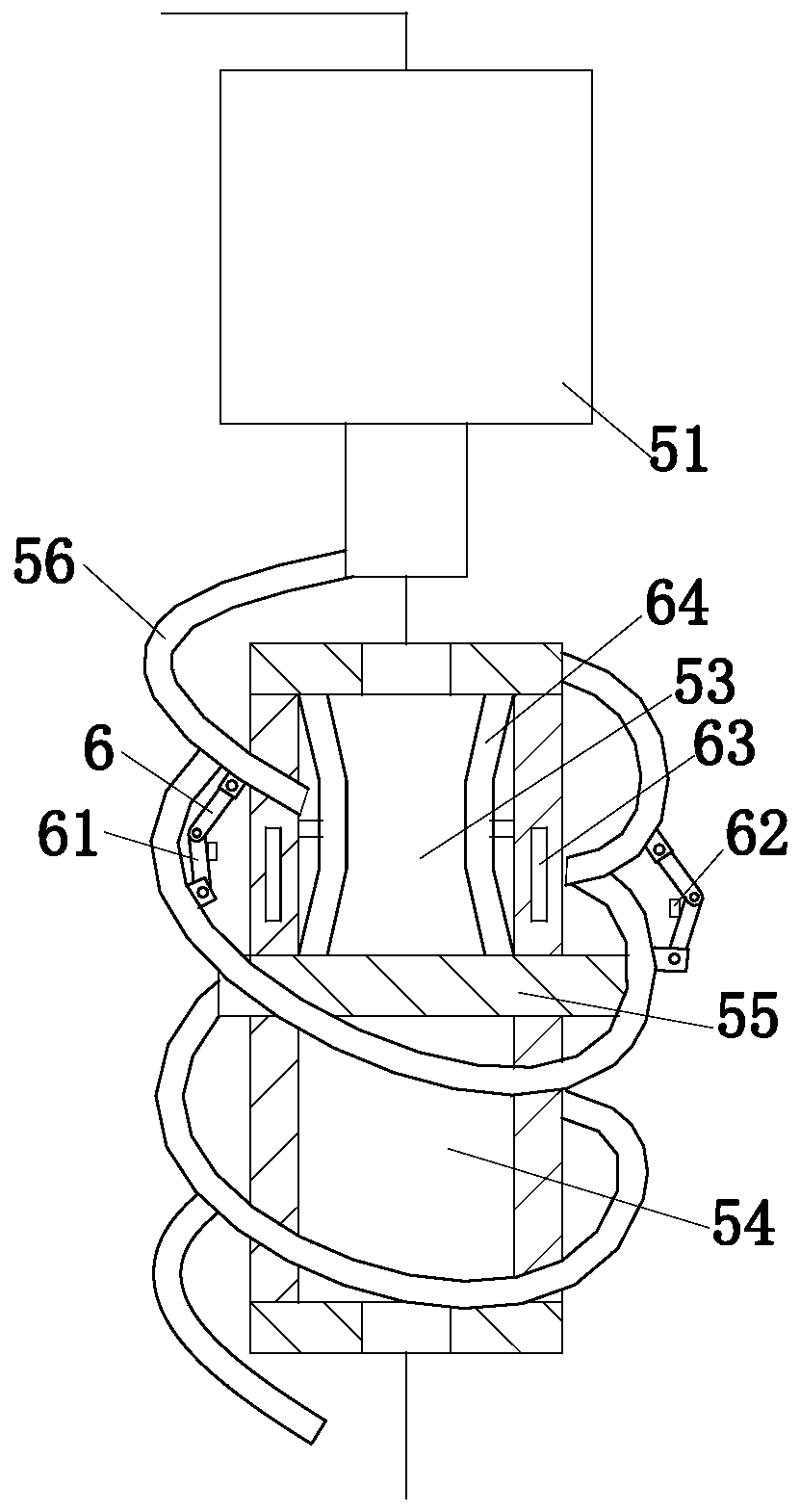
[0024] use Figure 1 to Figure 3 An optical teaching aid for an optical physics experiment of the present invention is described as follows.

[0025] Such as Figure 1 to Figure 3 As shown, an optical teaching aid for optical physics experiments according to the present invention includes a mounting frame 1 for small hole imaging, a projection screen 2, a light shield 3 and a light source module 4, and the projection screen 2 is located on the mounting frame 1 One end; the light source module 4 is located at the other end of the mounting frame 1, the light source module 4 and the projection screen 2 are all slidably connected with the mounting frame 1, and the light source module 4 is used to adjust the shape of the light source, so that the small hole imaging experiment is easy to observe; the said The shading plate 3 is located between the projection screen 2 and the light source module 4, the shading plate 3 is slidably connected with the installation frame 1, and the midd...


PUM


Abstract

The invention belongs to the physics teaching aid technical field, and specifically relates to an optical physics experiment optical teaching aid comprising a mount rack for pin-hole imaging, a projection screen, a shield plate, and a light source module; the projection screen is arranged on one end of the mount rack; the light source module is arranged on the other end of the mount rack; the light source module and the projection screen are respectively connected with the mount rack in a slide mode; the light source module is used for adjusting the light source shape, thus easily observing the pin-hole imaging test; the shield plate is arranged between the projection screen and the light source module, connected with the mount rack in a slide mode, and a hole 1 is arranged in the center of the shield plate. The two end positions of two LED lamp panels are changed, so two LED lamp panels in a regular shape of a Chinese character ba can be gradually changed into an inverted ba-shape, thus gradually changing changing the inserted ba-shape on the projection screen into a regular ba-shaped real image, realizing pin-hole imaging conversion, further enabling students to understand more of the pin-hole imaging principle, understanding the property that light travels in a straight line, and improving the teaching quality.

Description

technical field [0001] The invention belongs to the technical field of physics teaching aids, in particular to an optical teaching aid for optical physics experiments. Background technique [0002] Small hole imaging, about 2400 to 500 years ago, Chinese scholars - Mo Di (Mozi) and his students, did the world's first small hole into an inverted image experiment, explained the small hole into an inverted image. The cause of imagery points out the nature of light traveling in straight lines. This was the first scientific explanation for the straight-line propagation of light. If a plate with a small hole is used to cover the wall and the object, the reflection of the object will be formed on the wall. We call this phenomenon small hole imaging. Moving the middle plate back and forth changes the size of the image on the wall. This phenomenon illustrates the property of light traveling in a straight line. [0003] The pinhole imaging experiment is an important link in the exp...

Claims


Application Information

Patent Timeline
Patent Type & Authority Patents(China)
IPC IPC(8): G09B23/22
CPCG09B23/22
Inventor 李学超王兵曲忠伟王平叶纯宝
Owner ANHUI UNIV OF SCI & TECH
Why Eureka
Try Eureka