Condenser equipment for environmental engineering

An environmental engineering and condenser technology, applied in steam/steam condensers, heat exchange equipment, lighting and heating equipment, etc., can solve problems such as poor air filtration effect, blockage of heat dissipation area inside equipment, poor heat dissipation and cooling effect of equipment, etc. To achieve the effect of improving the condensation effect of steam, shortening the time required for air cooling, and improving the condensation effect

Inactive Publication Date: 2018-12-21
吕刚
View PDF2 Cites 0 Cited by
  • Summary
  • Abstract
  • Description
  • Claims
  • Application Information

AI Technical Summary

Problems solved by technology

[0006] In order to solve the above technical problems, the present invention provides a condenser device for environmental engineering to solve the problem that the existing condenser device has poor heat dissipation and cooling effect inside the device, and it is easy to cause the steam circulating inside the device to be unable to condense effectively , affecting the condensation effect inside the device; and the filtering effect of the air circulating inside the device is poor. During long-term use, the impurities contained in the air will easily block the heat dissipation area inside the device, affecting the heat dissipation effect inside the device

Method used


Image

  • Condenser equipment for environmental engineering
  • Condenser equipment for environmental engineering
  • Condenser equipment for environmental engineering

Examples


Embodiment

[0036] as attached figure 1 to attach Figure 10 Shown:

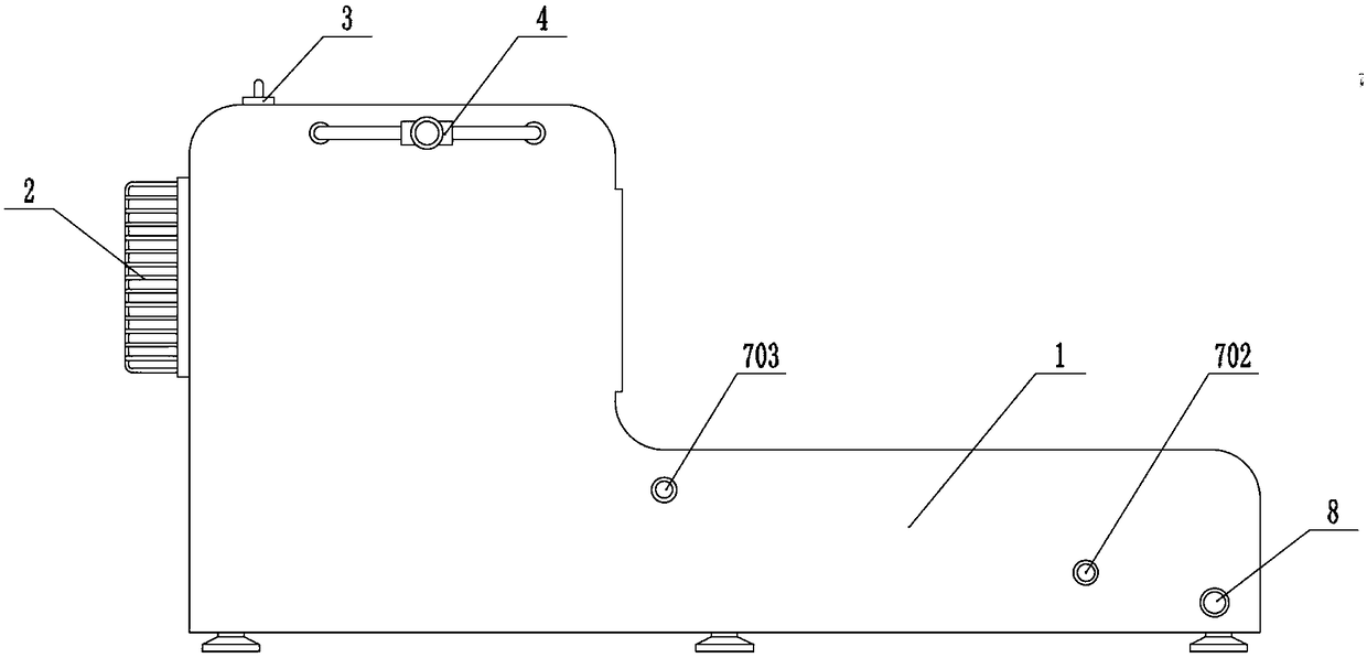
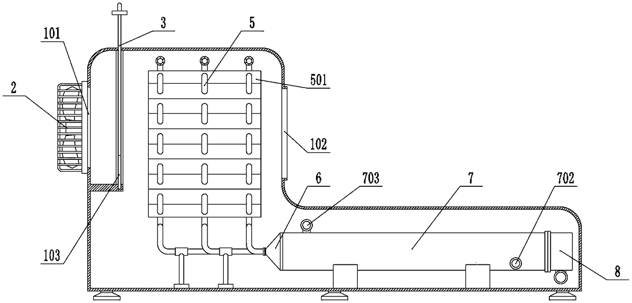
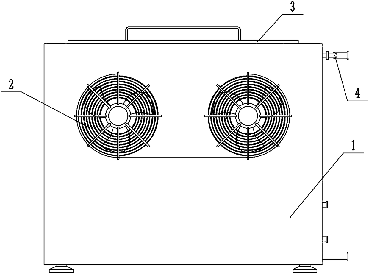
[0037]The invention provides a condenser device for environmental engineering, comprising a main body 1, an air inlet 101, an air outlet 102, a chute 103, a fan 2, a filter screen 3, an air inlet pipe 4, an air cooling pipe 5, and an air cooling fin 501, connecting pipe 6, water cooling column 7, water cooling channel 701, chilled water inlet 702, chilled water outlet 703, drain pipe 8 and blade 9; the rear end of the main body 1 is provided with two air inlets 101, and the top of the front end of the main body 1 An air outlet 102 is provided, and the air inlet 101 communicates with the air outlet 102; the left and right ends of the main body 1 are respectively provided with a chute 103, and the left and right ends of the filter screen 3 are respectively located in two chute 103 ; The fan 2 is installed on the main body 1, and the fan 2 is connected to the external control circuit through the power cord; The air-cool...


PUM


Abstract

The invention provides condenser equipment for environmental engineering. The condenser equipment comprises a water drain pipe and blades. The rear end of a main body is provided with two air inlets,the top of the front end of the main body is provided with an air outlet, and the air inlets communicate with the air outlet. The left and right ends in the main body are each provided with a slidinggroove, and the left and right ends of a strainer are located in the two sliding grooves correspondingly. A fan is installed on the main body and is connected with an outer control circuit through a power line. An air inlet pipe is installed on the left side end face of the main body and is connected with three air cooling pipes. Air cooling heat dissipation fins are connected with the three air cooling pipes correspondingly. A single stream of hot steam can be divided into three streams for heat dissipation cooling correspondingly, time needed by air cooling of the single stream of hot steamis shortened, the air cooling dissipation area in the equipment can be increased effectively through matched use of the air cooling heat dissipation fins, heat of the air cooling pipes can be fully released into air, and the cooling effect of the air cooling pipes is accelerated.

Description

technical field [0001] The invention belongs to the technical field of condensers, and more specifically relates to condenser equipment for environmental engineering. Background technique [0002] The condenser is a component of the refrigeration system and is a type of heat exchanger that can convert gas or vapor into liquid, and transfer the heat in the tube to the air near the tube in a very fast manner. The working process of the condenser is an exothermic process, so the temperature of the condenser is relatively high, and it is mostly used in the field of power plants to prevent the discharge of hot steam from causing harm to the external environment. [0003] Based on the above, the inventors found that in existing condenser equipment, such as a condenser (10) mentioned in Patent Application No. 201410641273.4, the inlet connector (22) (to which the refrigerant is supplied) is connected to the first The side wall of the header (12). The inlet connector (22) is dispo...

Claims


Application Information

Patent Timeline
Patent Type & Authority Applications(China)
IPC IPC(8): F28B1/02F28B1/06F28F19/01
CPCF28B1/02F28B1/06F28F19/01
Inventor 吕刚鲍佳敏高云
Owner 吕刚
Why Eureka
Try Eureka