Furnace discharging system for calcium carbide sensible heat power generation

A technology of calcium carbide and calcium carbide pot, which is applied in the direction of furnace, electric charge control, furnace components, etc., can solve the problems of energy waste, unfavorable energy saving and emission reduction, high maintenance cost, etc., to improve stability and safety, reduce track maintenance cost, and automate high degree of effect

Active Publication Date: 2018-12-25
DALAD BANNER BRANCH OF INNER MONGOLIA YILI ENERGYCO
View PDF10 Cites 4 Cited by
  • Summary
  • Abstract
  • Description
  • Claims
  • Application Information

AI Technical Summary

Problems solved by technology

The heat generated during the entire cooling process of calcium carbide is completely lost, resulting in energy waste, which is not conducive to energy saving and emission reduction
[0003] CN105217632A discloses a calcium carbide sensible heat recovery system, including a roller table, a quick-condensation shell, a roller tunnel kiln and waste heat recovery equipment, wherein the quick-condensation shell is installed on the roller table, and the quick-condensation shell is cooled by cooling water for cooling, the roller tunnel kiln is arranged on the roller table, and a circulating fan is installed in the roller tunnel kiln to circulate and air-cool the calcium carbide, and the waste heat recovery equipment is connected to the roller tunnel kiln through pipelines for waste heat recovery. recovery, the high-temperature liquid calcium carbide is injected from the tank into the quick-condensing shell for primary cooling, and the roller table transports the quick-condensing shell to the roller tunnel kiln for further cooling of the calcium carbide. The calcium carbide sensible heat recovery system requires Changing the existing production process, increasing the plant area, and large investment are not suitable for the calcium carbide field of orbital production
[0004] CN105716435A discloses a heat collection and recovery device for calcium carbide out of the furnace track, comprising a heat collecting cover (1), the heat collecting cover (1) is located above the calcium carbide out of the furnace track (2), when the calcium carbide trolley running to the heat collecting When the cover (1) is under the cover (1), the heat energy released by the calcium carbide on the calcium carbide trolley gathers in the heat collecting cover (1) to achieve the effect of heat energy recovery. This invention is suitable for the existing track-type calcium carbide production process, but the invention uses track cooling It needs to occupy a lot of space, so that the furnace system needs to arrange at least two straddles, and the track is full of calcium carbide pots. The plant area cannot be effectively used, and the investment is huge at one time, and the production rhythm cannot be further improved.
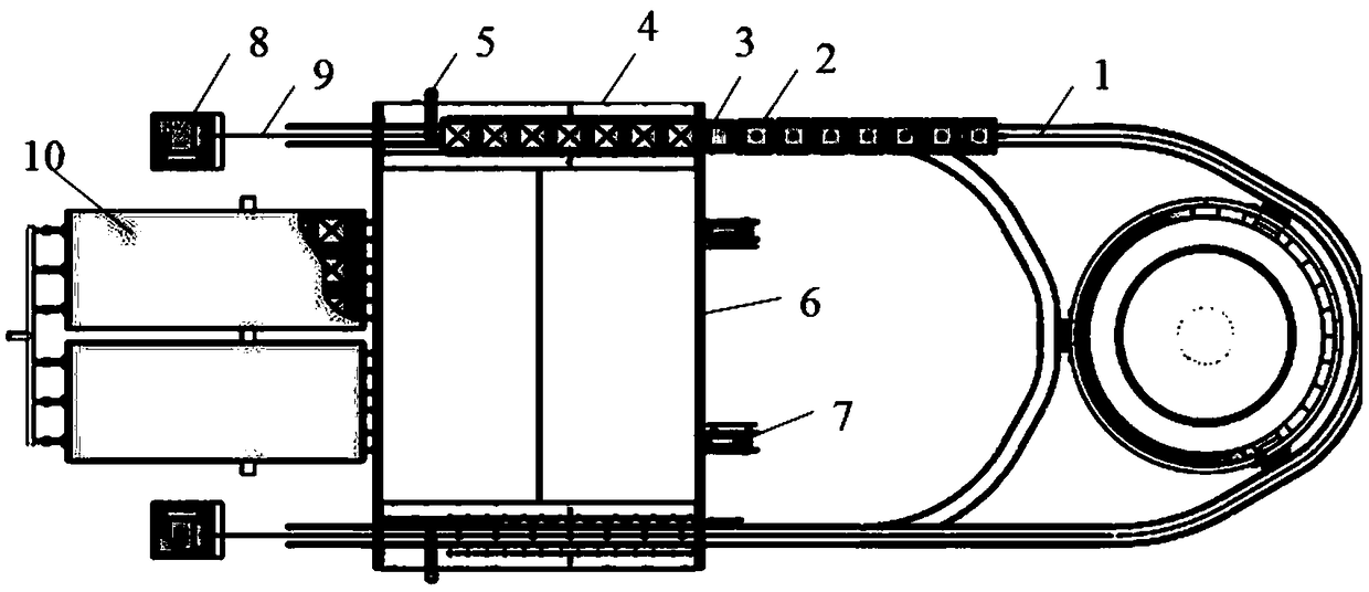
[0005] CN107176606A discloses a system for recovering sensible heat of calcium carbide liquid, comprising: calcium carbide furnace, the calcium carbide furnace has a carbonaceous material inlet, a calcium material inlet and a calcium carbide liquid outlet; a calcium carbide car, the calcium carbide car and the calcium carbide liquid outlet connected; a tunnel kiln, in which a track is arranged along the direction from the kiln head to the kiln tail, and the calcium carbide car is connected to the tunnel kiln and can travel along the kiln head to the kiln on the track The kiln head is arranged with a plurality of inert gas injection holes, the kiln tail is arranged with a plurality of heated inert gas injection holes, and the side wall of the tunnel kiln is equipped with a water-cooled wall, and the water-cooled wall has a cold water Inlet and hot water outlet, both ends of the kiln head and the kiln tail are sealed, and the kiln head is provided with a calcium carbide car moving device; the calcium carbide unloading device is arranged near the kiln tail and is connected with the kiln tail. The carbide carts are connected, and the calcium carbide sensible heat recovery system can be applied to the rail-type calcium carbide production process, and it occupies a small space and has a good waste heat 
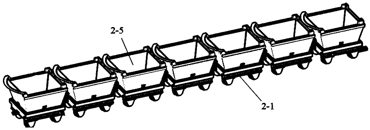
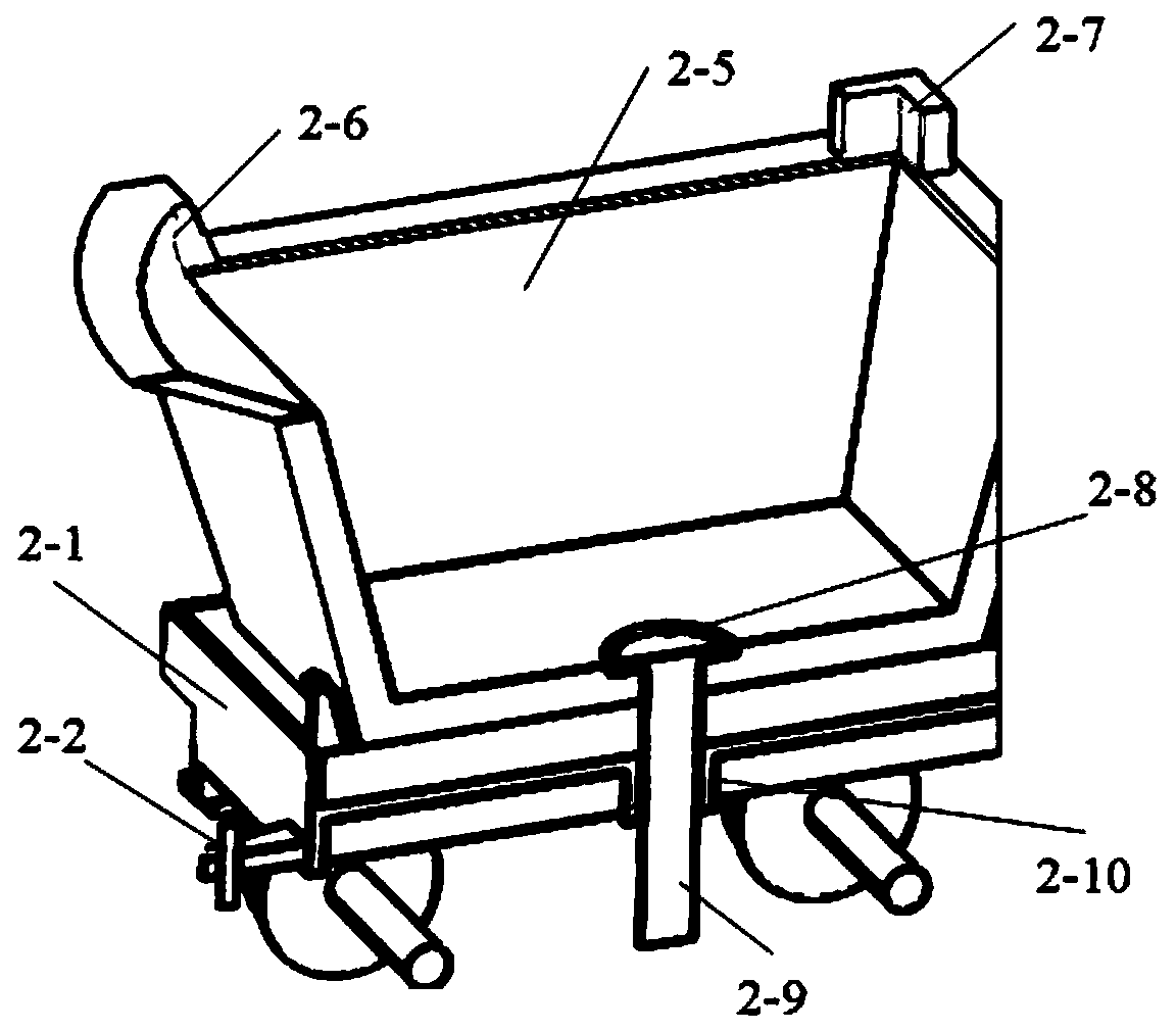
recovery effect. However, this invention does not elaborate on the calcium carbide carts, which are key components of the system. Some calcium carbide vehicles are difficult to achieve continuous and reliable operation of the system, the sensible heat loss during transportation is large, and the recovery effect is poor
[0006] Calcium carbide production is produced once an hour on average. Therefore, the transportation device of calcium carbide liquid is the key to the normal operation of the system. However, the current calcium carbide truck is intermittently transported, with low efficiency, many control points, complicated operation, and chances of failure. It is relatively large, the maintenance cost is high, and the maintenance time is long. The calcium carbide liquid is easy to fall on the ground between the tracks through the gap between the two calcium carbide pots, and it is troublesome to clean up.

Method used


Image

  • Furnace discharging system for calcium carbide sensible heat power generation
  • Furnace discharging system for calcium carbide sensible heat power generation
  • Furnace discharging system for calcium carbide sensible heat power generation

Examples


Embodiment Construction

[0048] It should be understood that the specific embodiments described here are only used to explain the present invention, not to limit the present invention. It should be noted that, in the description of the present invention, the terms "horizontal", "vertical", "upper", "lower", "front end", "rear end", "left", "right", "vertical" , "horizontal", "inner", "outer" and other indicated orientations or positional relationships are based on the orientations or positional relationships shown in the drawings, which are only for the convenience of describing the present invention and simplifying the description, and are not indicative or implied. No device or element must have a specific orientation, be constructed, and operate in a specific orientation and therefore should not be construed as limiting the invention.

[0049] The realization, functional characteristics and advantages of the present invention will be further described below in conjunction with the accompanying draw...


PUM


Abstract

The invention discloses a furnace discharging system for calcium carbide sensible heat power generation. The furnace discharging system comprises a conveying track, a furnace discharging trolley set,a moving platform, a mechanical arm, a traction track, traction trolleys, winches and a tunnel kiln. The moving platform is connected with the conveying track and the traction track. The front end andthe rear end of the furnace discharging trolley set are connected with one ends of two steel wire ropes correspondingly. The other ends of the two steel wire ropes are connected with the winches correspondingly. Under driving of the winches, the furnace discharging trolley set reciprocates on the conveying track. The mechanical arm is located on the outer side of the moving platform so that the front end or the rear end of the furnace discharging trolley set can be disconnected from and connected with the steel wire ropes. The traction trolleys are located on a traction trolley track on the outer side of the traction track. The tunnel kiln is internally provided with a track corresponding to the moving platform. The winches are located on the two sides of the tunnel kiln. The furnace discharging system has the beneficial effects that continuous conveying and unloading can be achieved, efficiency is high, running is automatic, operation is simple, the running cost is low, and running is stable.

Description

technical field [0001] The invention relates to the technical field of waste heat utilization, in particular to a furnace tapping system for calcium carbide sensible heat power generation. Background technique [0002] In the traditional calcium carbide production, when the calcium carbide is released from the furnace, the calcium carbide pot is carried on the trolley, and the calcium carbide pot is led to the calcium carbide outlet by the traction device. When it comes out of the furnace, molten calcium carbide flows into each calcium carbide pot, and the temperature of the liquid calcium carbide at this time is above 1300°C. After being out of the furnace, the calcium carbide pot filled with molten calcium carbide is pulled into the cooling workshop for cooling. When the temperature drops to about 400°C, the calcium carbide solidifies and forms, and is lifted out of the calcium carbide pot and transported to the storage workshop for further cooling. The heat generated dur...

Claims


Application Information

Patent Timeline
Patent Type & Authority Applications(China)
IPC IPC(8): F27D3/02F27D3/12
CPCF27D3/026F27D3/123
Inventor 魏强李小军郭宝山李治国段成旺徐世平
Owner DALAD BANNER BRANCH OF INNER MONGOLIA YILI ENERGYCO
Why Eureka
Try Eureka