
Design method of optical integrator

A technology of optical integrator and design method, which is applied in the field of optical integrator, can solve problems such as limited distance, and achieve the effect of meeting simulation requirements, improving the uniformity of irradiating body, and good simulation requirements

Active Publication Date: 2019-01-01
BEIJING INST OF ENVIRONMENTAL FEATURES
View PDF4 Cites 2 Cited by
  • Summary
  • Abstract
  • Description
  • Claims
  • Application Information

AI Technical Summary

Problems solved by technology

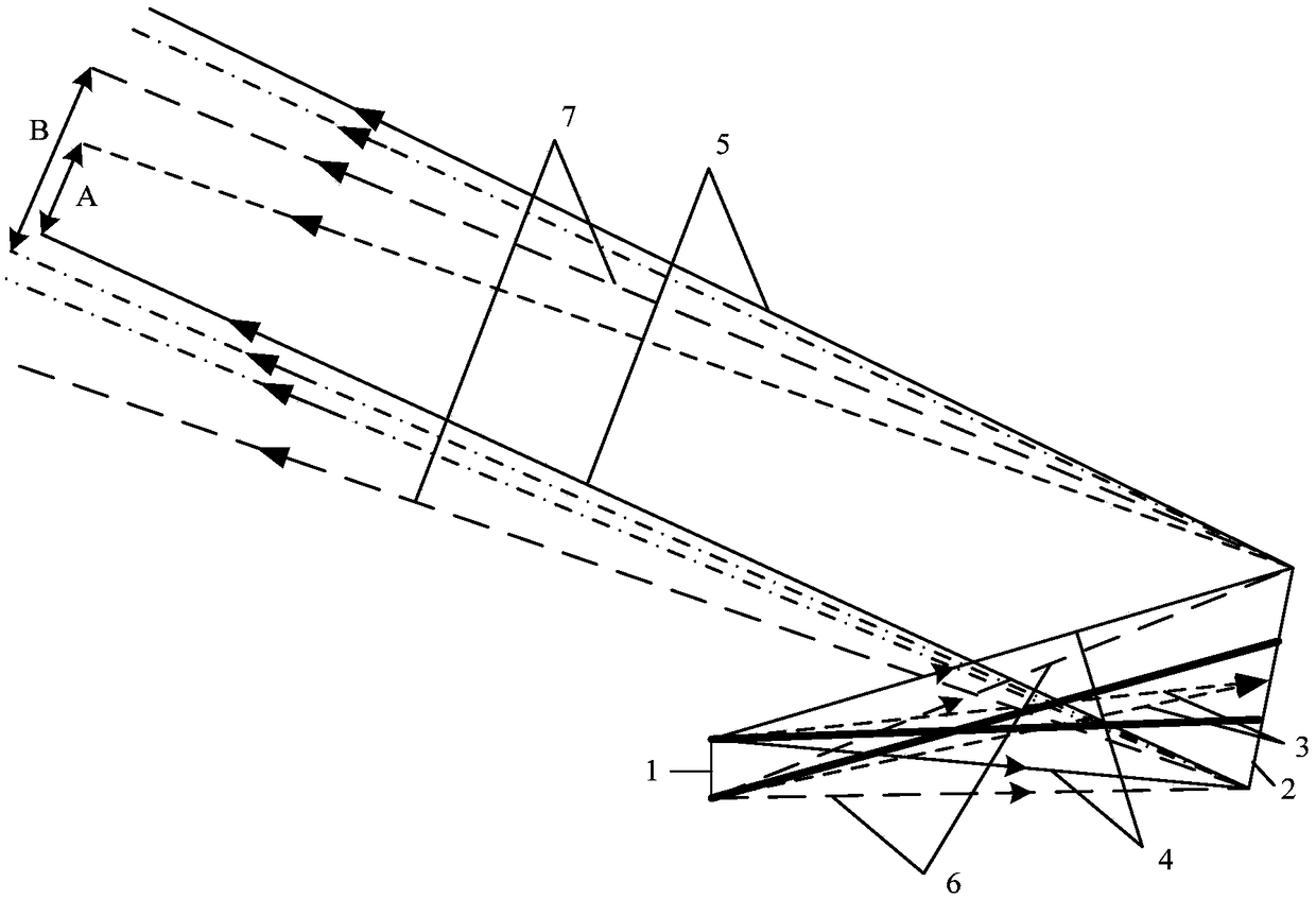
[0006] The technical problem to be solved by the present invention is that the lens units in the existing optical integrator are arranged in the form of a spherical surface, so that the optical axes of each channel converge on the main optical axis, and the distance between the reference irradiation uniform surface and the collimating mirror is limited defects, providing a design method for optical integrators

Method used


Image

  • Design method of optical integrator
  • Design method of optical integrator

Examples


Embodiment Construction

[0018] In order to make the purpose, technical solutions and advantages of the embodiments of the present invention clearer, the technical solutions in the embodiments of the present invention will be clearly and completely described below in conjunction with the drawings in the embodiments of the present invention. Obviously, the described embodiments It is a part of embodiments of the present invention, but not all embodiments. Based on the embodiments of the present invention, all other embodiments obtained by persons of ordinary skill in the art without making creative efforts belong to the protection scope of the present invention.

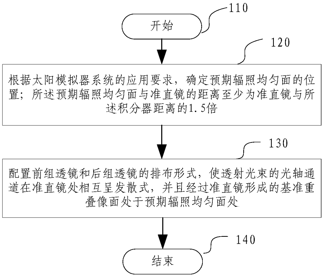
[0019] The invention provides a design method of an optical integrator, combining figure 1 As shown, the design method includes:

[0020] The design method starts at step 110;

[0021] Then perform step 120, according to the application requirements of the solar simulator system, determine the position of the expected uniform irradiation su...


PUM


Abstract

The invention relates to a design method of an optical integrator, which comprises the steps of determining the position of an expected irradiation uniform plane according to application requirementsof a solar simulator system, wherein the distance between the expected irradiation uniform plane and a collimating mirror is at least 1.5 times of the distance between the collimating mirror and the optical integrator; and configuring the arrangement form of a front lens group and a rear lens group so as to enable optical axis channels of transmitted beams to be in mutual divergence at the collimating mirror, wherein a reference overlapping image plane formed by the collimating mirror is located at the expected irradiation uniform plane. Compared with the existing integrator form in which theoptical axes converge at a point, the method of the invention changes the position of the irradiation uniform plane of the system, thereby being capable of greatly meeting the use requirement of a large distance between the irradiation uniform plane and the collimating mirror.

Description

technical field [0001] The invention relates to the technical field of optical integrators, in particular to a design method of an optical integrator. Background technique [0002] The solar simulator can simulate the luminous characteristics of the real sun and is used to simulate the solar radiation in the outer space of the earth. It can realistically reproduce the collimation, uniformity and spectral characteristics of the solar radiation in the space environment in the ground laboratory. The solar simulator is mainly composed of a light source, a condenser reflector, an optical integrator, and a collimator. Simulation of the sun at infinity. [0003] As a key component to make the solar simulator produce a uniform irradiated surface, the optical integrator is located between the concentrating mirror and the collimating mirror, which can effectively improve the optical uniformity of the illumination. The optical integrator mainly includes two groups of lenses. The fron...

Claims


Application Information

Patent Timeline
Patent Type & Authority Applications(China)
IPC IPC(8): G02B27/00G02B27/09G02B5/02
CPCG02B5/02G02B27/0012G02B27/0955
Inventor 陈红彭月王景峰苏必达华昊邓蓉
Owner BEIJING INST OF ENVIRONMENTAL FEATURES
Learn More