Sewing machine

A sewing machine and sewing department technology, applied in the direction of sewing machine components, sewing equipment, tension devices, etc., can solve the problems of shortening the transmission interval of driving signals, discreteness, and the inability of the sewing machine to smoothly control the rotation position of the pulse motor

Active Publication Date: 2019-01-04
BROTHER KOGYO KK
View PDF6 Cites 11 Cited by
  • Summary
  • Abstract
  • Description
  • Claims
  • Application Information

AI Technical Summary

Problems solved by technology

Therefore, when the pulse motor is driven, the rotational position of the output shaft to reach the target becomes discrete, and the sewing machine may not be able to smoothly control the rotational position of the output shaft of the pulse motor.
When the transmission interval of the drive signal is shortened and the width of the rectangular wave is reduced in order to control the rotational position of the output shaft with high precision, the output shaft of the pulse motor may not be able to follow the high-speed sewing operation of the sewing machine.
That is, the output shaft of the pulse motor may not rotate stably

Method used


Image

  • Sewing machine
  • Sewing machine
  • Sewing machine

Examples


Embodiment Construction

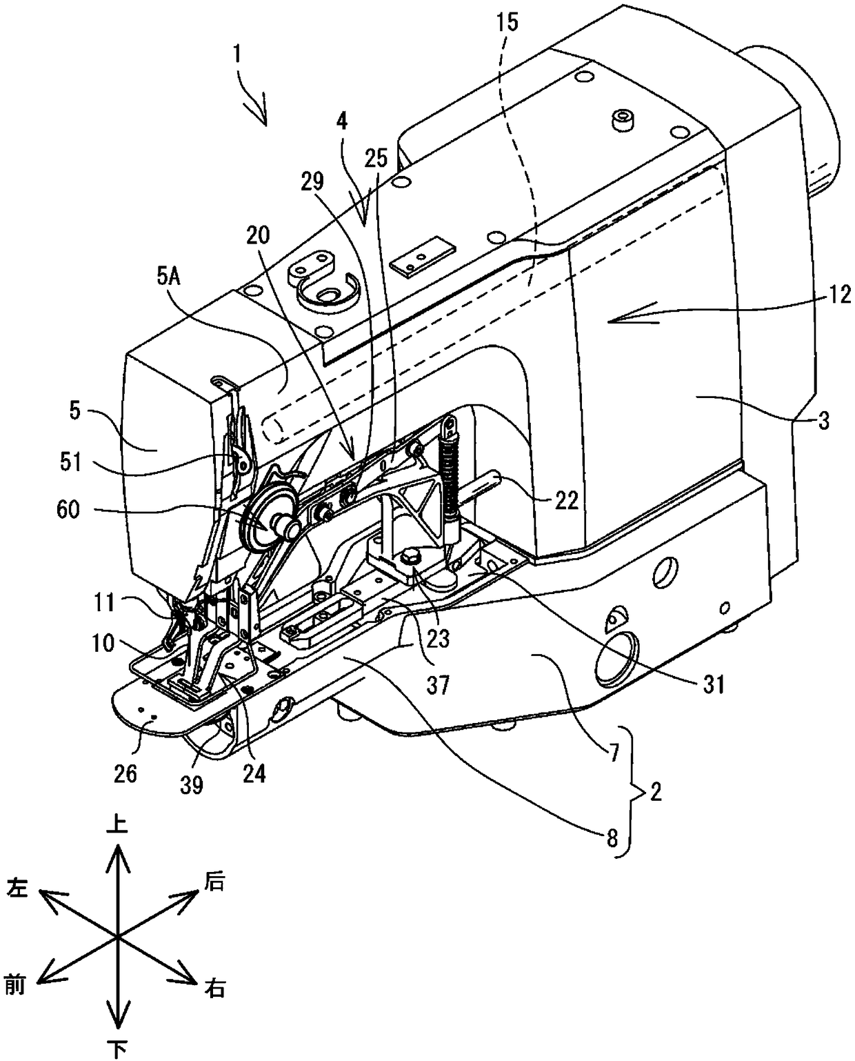
[0030] The embodiments of the present invention will be described below. The following description uses the left and right, front and back, and up and down indicated by arrows in the figure. figure 1 The sewing machine 1 shown is used for fabric 105 (refer to Figure 6A ) To form a knotting machine with reinforcement stitches.

[0031] Reference Figure 1 ~ Figure 3 , The schematic structure of the sewing machine 1 will be described. The sewing machine 1 has a base 2, a support 3, and an arm 4. The machine base 2 is the base of the sewing machine 1 and is arranged on a horizontally extending workbench. The base portion 2 has a base body portion 7 and a cylindrical base portion 8. The main body portion 7 of the machine base is substantially box-shaped. The cylindrical seat portion 8 extends forward from the base body portion 7. The inside of the stand main body 7 and the inside of the cylindrical seat 8 communicate with each other. The cylindrical seat portion 8 has a needle ...


PUM


Abstract

The invention relates to a sewing machine, which enables an output shaft of a motor, adjusting facial suture tension, to stably follow the sewing action for rotation. The sewing machine comprises a wire-clamping motor and a wire-clamping plate. The wire-clamping plate is fixed to an output shaft of the wire-clamping motor. An operator winds the facial suture to the wire-clamping plate. The wire-clamping motor conducts rotation drive, and changes the tension of the facial suture. The CPU of the sewing machine determines the electrifying module of each coil of the wire-clamping motor based on the detection result of the encoder. The CPU electrifies the plurality of coils of the wire-clamping motor by means of the determined electrifying module, so as to control the driving of the wire-clamping motor. Every time when the CPU determines the electrifying mode, a plurality of coils can be electrified.

Description

Technical field [0001] The invention relates to a sewing machine. Background technique [0002] Known is a sewing machine that uses a pulse motor to control the tension of the upper thread during sewing. The sewing machine disclosed in Japanese Patent Publication No. 89823 in 2009 has a pulse motor, a pulse motor drive unit, a thread clamping plate, an encoder, an operation panel, and a sewing machine motor. The pulse motor has an output shaft. The sewing machine controls the driving of the pulse motor by inputting driving pulses to the pulse motor driving section. The clamping plate is fixed to the output shaft. The thread clamping plate can wind the upper thread. The encoder is used to detect the rotational position of the output shaft. The operator uses the operation panel to input the upper thread tension into the sewing machine. Driven by the sewing machine motor, the sewing machine executes the sewing operation. When the sewing machine motor is driven, the sewing mac...

Claims


Application Information

Patent Timeline
Patent Type & Authority Applications(China)
IPC IPC(8): D05B47/04
CPCD05B47/04
Inventor 竹村徹中野元就
Owner BROTHER KOGYO KK
Why Eureka
Try Eureka