
A multi-core cable splitter

A multi-core cable and splitter technology, which is applied in the direction of electrical components, clamping/spring connections, etc., can solve the problems of bulky junction boxes, wire connection processing, and waste of junction boxes, etc., to achieve flexible settings and cost savings , Simple and compact structure

Pending Publication Date: 2019-01-11
GUANGZHOU PANYU CABLE WORKS
View PDF0 Cites 1 Cited by
  • Summary
  • Abstract
  • Description
  • Claims
  • Application Information

AI Technical Summary

Problems solved by technology

[0002] In today's society, it is very important to use electricity safely and ensure the safe and stable operation of the power grid. The poor connection of wires has brought a lot of trouble to people.
When connecting power transmission and distribution lines, it is often necessary to connect multi-core cables to the junction box and lead out the cores of each phase through the junction box. This method will cause the following problems: The entire multi-core cable is cut off and the cores of each phase are connected and led out, which is prone to lead connection processing problems in the wiring, and when there is a problem with the connection of the distribution box, all downstream power supplies are affected; when only a certain phase core needs to be led out on site , using a junction box will cause waste; the junction box is large in size and high in cost, resulting in waste of space and cost

Method used


Image

  • A multi-core cable splitter
  • A multi-core cable splitter
  • A multi-core cable splitter

Examples


Embodiment 1

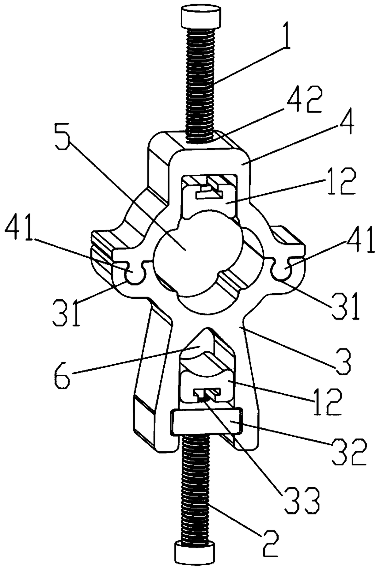
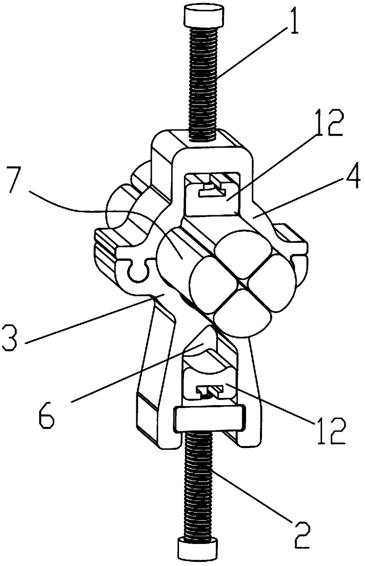
[0023] Such as figure 1 , 2 As shown, a multi-core cable splitter includes a wire core fixing seat 3, a cable fixing frame 4, a first bolt 1 and a second bolt 2, and the two sides of one end of the wire core fixing seat 3 are respectively provided with through-type plugs. Slots 31, the two sides of the cable fixing frame 4 are provided with corresponding convex strips 41, through the embedded fit of the convex strips 41 and the slots 31, the wire core fixing seat 3 and the cable fixing frame 4 are detachably connected, and the wires The core fixing seat 3 cooperates with the cable fixing frame 4 to form a main line cavity 5 for the multi-core cable 7 to pass through. The cable fixing frame 4 is provided with a first screw hole 42, and the first bolt 1 passes through the first screw hole 42 and connects with it. Threaded connection, and the front end of the first bolt 1 faces the wire core fixing seat 3 so as to be able to cooperate to press and fix the multi-core cable 7 in t...

Embodiment 2

[0027] On the basis of the technical solution of embodiment 1, the first bolt 1 and the second bolt 2 are improved as follows:

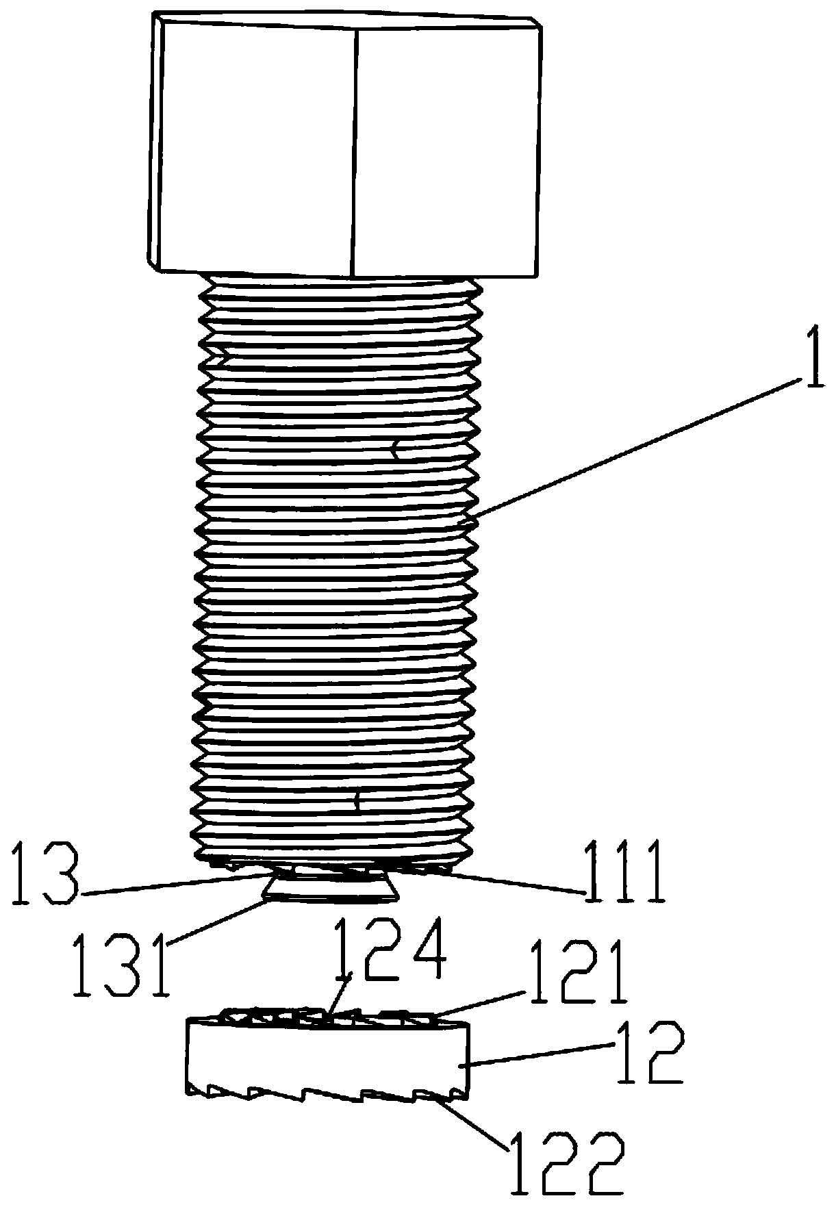
[0028] Such as image 3 As shown, taking the first bolt 1 as an example, the front end surface of the bolt and the back surface of the anti-slip pressure plate 12 are respectively provided with a first anti-reverse helical tooth 111 and a second anti-reverse helical tooth 121 that can engage with each other. , the first anti-reverse helical teeth 111 are circumferentially distributed on the front end face of the bolt to form a first ring gear, and the second anti-reverse helical teeth 121 are circumferentially distributed on the back of the anti-skid pressure plate 12 The second ring gear is formed. The first ring gear and the second ring gear are arranged opposite to each other. The first anti-reverse helical tooth 111 is inclined in the direction opposite to the tightening direction of the corresponding bolt, and the direction of the second anti-re...

Embodiment 3

[0033] On the basis of the technical solution of embodiment 2, the first bolt 1 and the second bolt 2 are further improved:

[0034] Such as Figure 4 As shown, taking the first bolt 1 as an example, the rear end of the bolt is provided with a first screw head 112 and a second screw head 113 in sequence along the axial direction, and a screw head 112 and a second screw head 113 are arranged between The broken part 114, the maximum torque that the broken part 114 can bear is less than the maximum torque that other parts of the bolt can bear, when the torque that the first screw head 112 bears is greater than the maximum torque that the broken part 114 can bear, the broken part 114 will break and thus The first screw head 112 is disengaged from the bolt. The structure of the fracture part 114 is an annular groove 1141 arranged on the outer surface of the bolt and an inner hole 1142 arranged inside the bolt, so that the wall thickness of the fracture part 114 is relatively small...


PUM


Abstract

The present invention relate to the field of power tool, in particular to a multi-core cable splitter, including a core fixing base, a cable fixing bracket, a first bolt and a second bolt, one end ofthe core fixing bracket is detachably connected with the cable fixing bracket and cooperatively forms a main wire cavity through which the cable passes, the first bolt is threadably connected with thecable fixing bracket, and the front end of the first bolt faces the core fixing bracket so as to cooperatively press and fix the cable in the main wire cavity. The other end of the core fixture is provided with a shunt cavity through which the core passes, a second bolt is threaded through and connected to the wall of the shunt cavity, and a front end of the second bolt faces the wall of the shunt cavity so as to be able to cooperate in pressing and fixing the core in the shunt cavity. The invention has the advantages of flexible arrangement, simple and compact structure, cost saving, and canreplace the branch box, and the multi-core cable does not need to be cut off completely and each phase wire core is connected, and the wire connection problem in the connection does not occur, and the downstream power supply is not affected.

Description

technical field [0001] The invention relates to the field of power tools, in particular to a multi-core cable splitter. Background technique [0002] In today's society, it is very important to use electricity safely and ensure the safe and stable operation of the power grid. The poor handling of wire connections has brought a lot of trouble to people. When connecting power transmission and distribution lines, it is often necessary to connect multi-core cables to the junction box and lead out the cores of each phase through the junction box. This method will cause the following problems: The entire multi-core cable is cut off and the cores of each phase are connected and led out, which is prone to problems in the connection of wires in the wiring, and when there is a problem with the connection of the distribution box, the downstream power supply is all affected; when only a certain phase core needs to be led out on site , The use of the junction box will cause waste; the j...

Claims


Application Information

Patent Timeline
Patent Type & Authority Applications(China)
IPC IPC(8): H02G3/08H01R4/46
CPCH01R4/46H02G3/08
Inventor 黄应敏胡超强尤占山邵源鹏高伟光刘金勇张仕欢王廷发冯家杰
Owner GUANGZHOU PANYU CABLE WORKS
Learn More