Slurry conditioning system of zero-wastewater-discharge device and operation method thereof

A zero-emission, conditioning technology, applied in dissolution methods, chemical instruments and methods, mixers with rotary stirring devices, etc., can solve the problems of insufficient dissolution of slaked lime, excessive supply of slaked lime, unstable system operation, etc. Dissolution speed, dissolving promotion, dissolving uniform effect

Pending Publication Date: 2019-01-15
BEIJING GUODIAN LONGYUAN ENVIRONMENTAL ENG
View PDF6 Cites 1 Cited by
  • Summary
  • Abstract
  • Description
  • Claims
  • Application Information

AI Technical Summary

Problems solved by technology

[0005] The purpose of the present invention is to provide a slurry conditioning system of a waste water zero-discharge device and its operating method, to solve the technical problem of vicious circle caused by hydrated lime floating on the surface of the concentrated slurry due to insufficient dissolution; and to solve the problem of excessive supply of hydrated lime and poor system operation stability problem

Method used


Image

  • Slurry conditioning system of zero-wastewater-discharge device and operation method thereof
  • Slurry conditioning system of zero-wastewater-discharge device and operation method thereof
  • Slurry conditioning system of zero-wastewater-discharge device and operation method thereof

Examples


Embodiment Construction

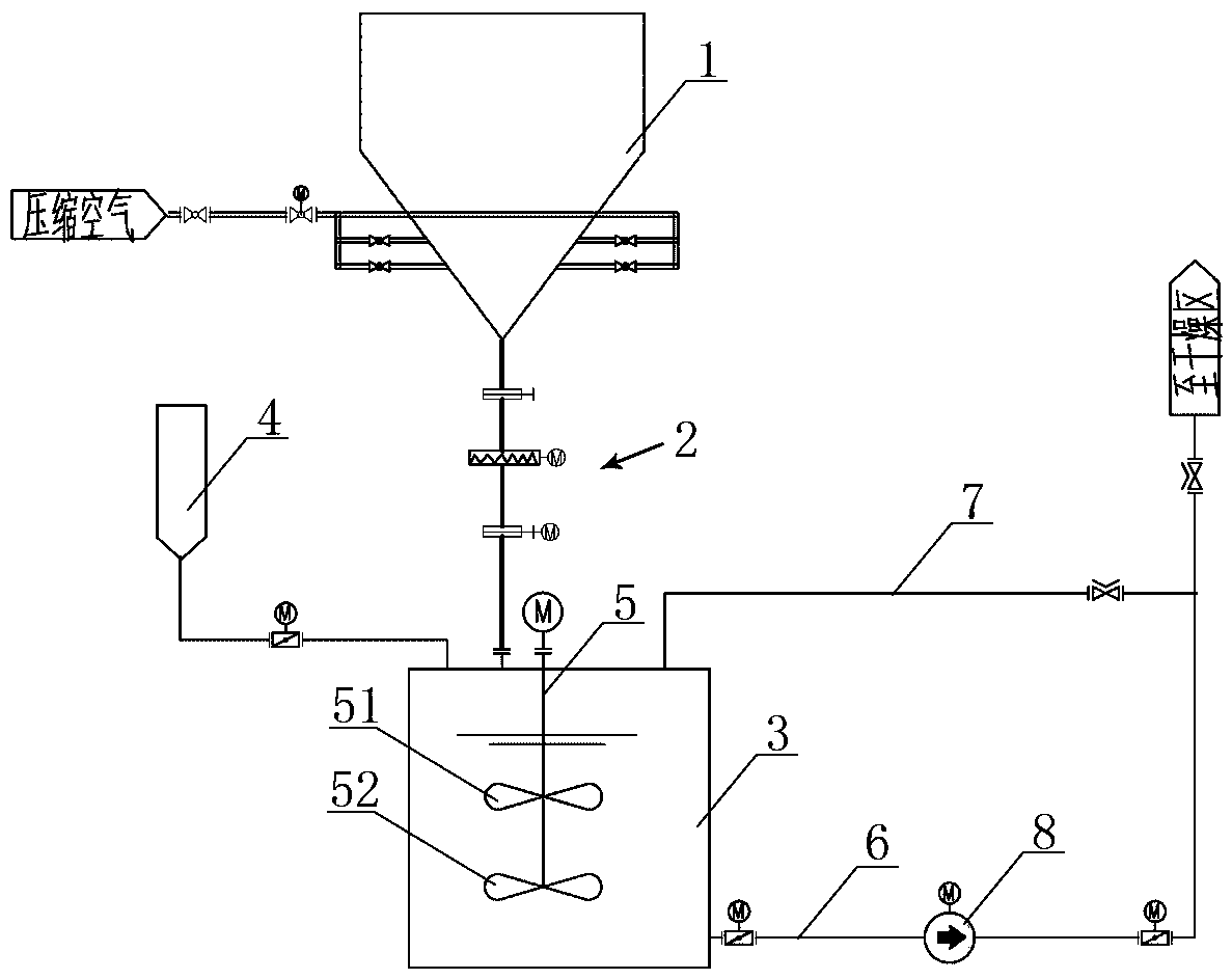
[0036] Examples see figure 1 As shown in the figure, the slurry conditioning system of this waste water zero-discharge device consists of slaked lime powder bin 1, feeding system 2, and conditioning box 3 connected in sequence from top to bottom, and the conditioning box 3 is connected with a thick slurry inlet pipe Road 4, quenched and tempered slurry outlet pipeline 6 and return pipeline 7, a stirrer 5 is arranged in the quenched and tempered tank 3, and a mixing pump 8 is arranged on the quenched and tempered slurry outlet pipeline 6.

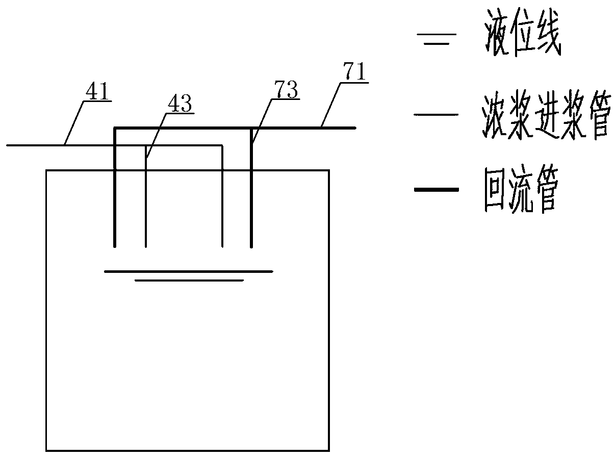
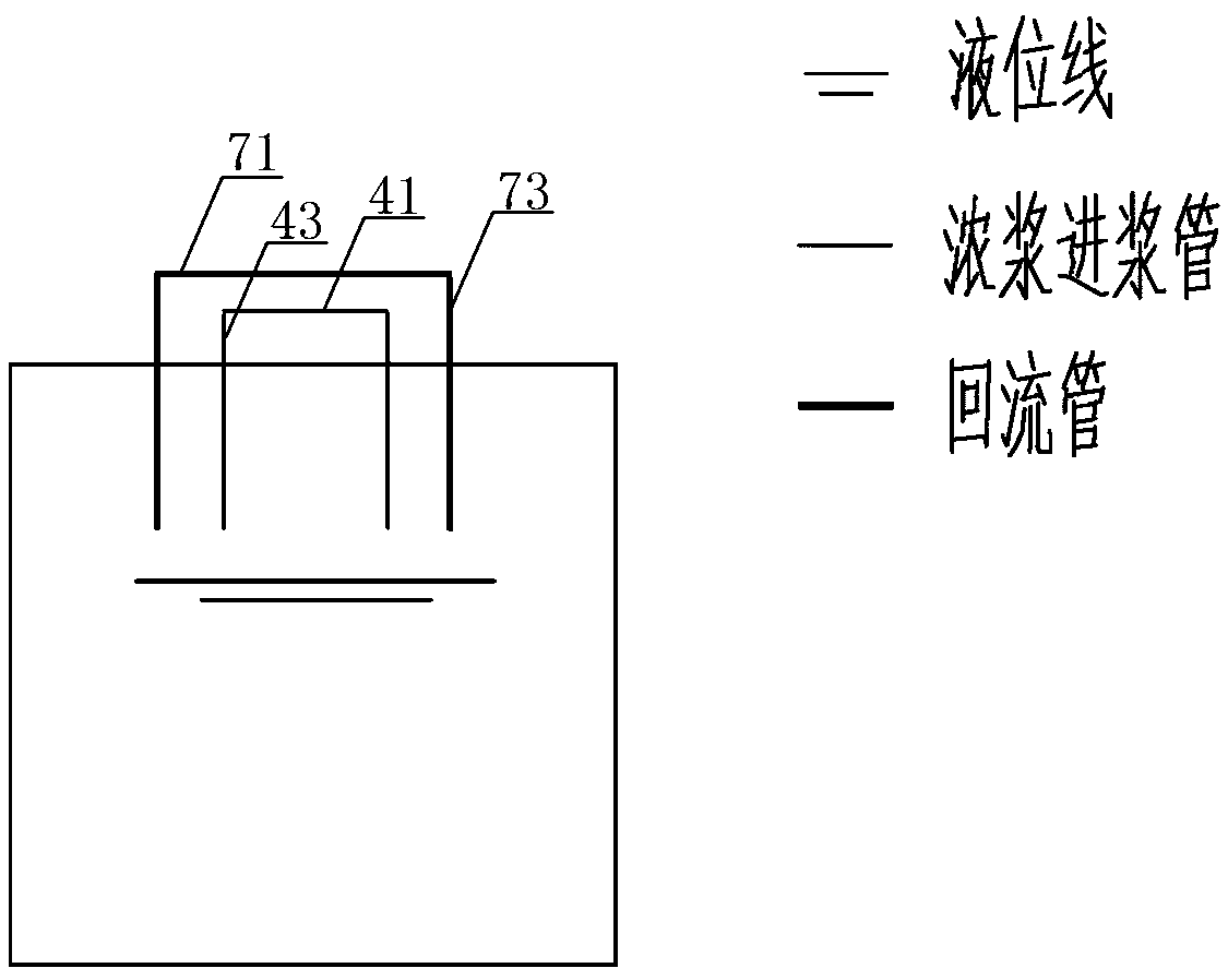
[0037] The thick stock feed pipeline 4 has a main pipe 41, the main pipe is divided into at least two parallel and spaced horizontal sub-pipes 42 above the quenching and tempering box, and a group of vertical sub-pipes are arranged in parallel and spaced on each horizontal sub-pipe 43. The vertical sub-pipe passes vertically downward through the top of the tempering box and communicates with the interior of the tempering box.

[0038] The r...


PUM

PropertyMeasurementUnit
diameteraaaaaaaaaa
heightaaaaaaaaaa

Abstract

The invention discloses a slurry conditioning system of a zero-wastewater-discharge device and an operation method thereof. The slurry conditioning system comprises a slaked lime powder bin, a feedingsystem and a conditioning box sequentially communicating with each other from top to bottom, wherein the conditioning box communicates with a thick slurry feeding pipeline, a conditioned slurry outlet pipeline and a return pipeline; an agitator is arranged in the conditioning box; and a mixing pump is arranged on the conditioned slurry outlet pipeline. The invention provides an improved scheme for the slurry conditioning system of a device used for zero discharging of the wastewater of a thermal power generating unit; the improved slurry conditioning system can improve the sufficient dissolving of slaked lime in concentrated slurry and promote conditioning effect, and avoids vicious circulation caused by floating of the slaked lime on the surface of the concentrated slurry due to delayeddissolution of the slaked lime; at the same time, the slurry conditioning system also avoids influence on the operation stability of the system caused by deposition of the slaked lime on the bottom ofthe conditioning box due to excessive supply of slaked lime powder when the slaked lime powder is not sufficiently dissolved or not dissolved in time; and the slurry conditioning system greatly improves the sufficiency and timeliness of a conditioning reaction, is enhanced in system stability, reduces the consumption of the slaked lime powder, and can be extensively applied to thick slurry conditioning units in devices for zero discharging of the wastewater of thermal power generating units.

Description

technical field [0001] The invention relates to the technical field of thermal power generation, in particular to a thermal power unit wastewater zero discharge device and an operating method thereof. Background technique [0002] The thermal power unit wastewater zero discharge device is divided into three main units: flue gas concentration, thick slurry conditioning, and slurry drying. Since the pH value of the concentrated slurry after the flue gas concentration is extremely low, in order to ensure the stability of the pipeline and equipment operation in the drying area And safety, before entering the drying area, it is necessary to increase the pH value of the concentrated slurry by adding slaked lime for conditioning. [0003] The currently commonly used slurry conditioning system includes a conditioning box, a single-layer agitator, a mixing pump, and a slurry return pipe to the top of the conditioning box: the thick slurry inlet pipe enters from the top of the conditi...

Claims


Application Information

Patent Timeline
Patent Type & Authority Applications(China)
IPC IPC(8): B01F7/18B01F13/10B01F15/02B01F1/00
CPCB01F21/30B01F21/02B01F21/10B01F27/112B01F27/191B01F33/82B01F27/90B01F35/71B01F35/75
Inventor 江清潘张启玖陈鸥曹洪兴蔡明明
Owner BEIJING GUODIAN LONGYUAN ENVIRONMENTAL ENG
Why Eureka
Try Eureka