
Semi-automatic balloon tube pre-forming machine and method
A preformer, balloon tube technology, applied in other manufacturing equipment/tools, manufacturing tools and other directions, can solve the problems of low accuracy, manual positioning of stretching distance, high labor intensity, etc., to achieve precise product quality control, liberation The effect of labor intensity and labor cost saving
- Summary
- Abstract
- Description
- Claims
- Application Information
AI Technical Summary
Problems solved by technology
Method used
Image

Examples
Embodiment Construction
[0034] The present invention will be further described in detail below with reference to the drawings and specific embodiments.
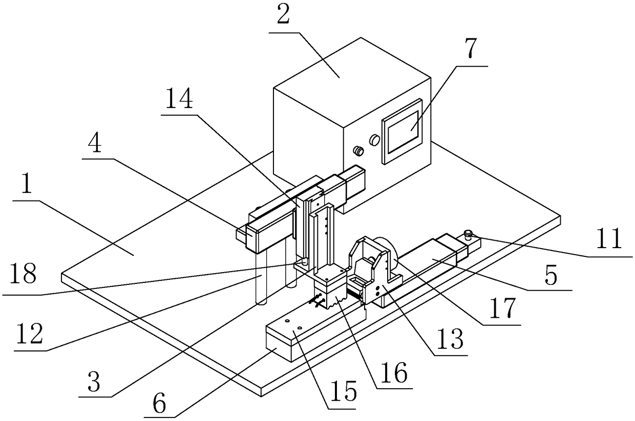
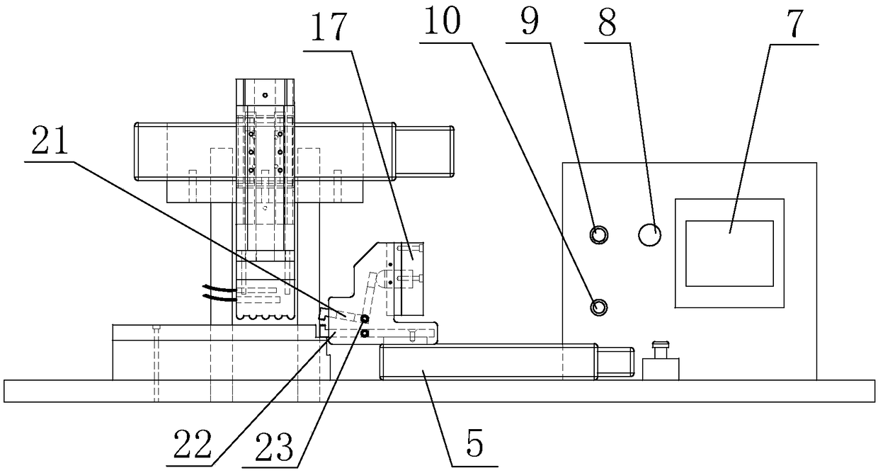
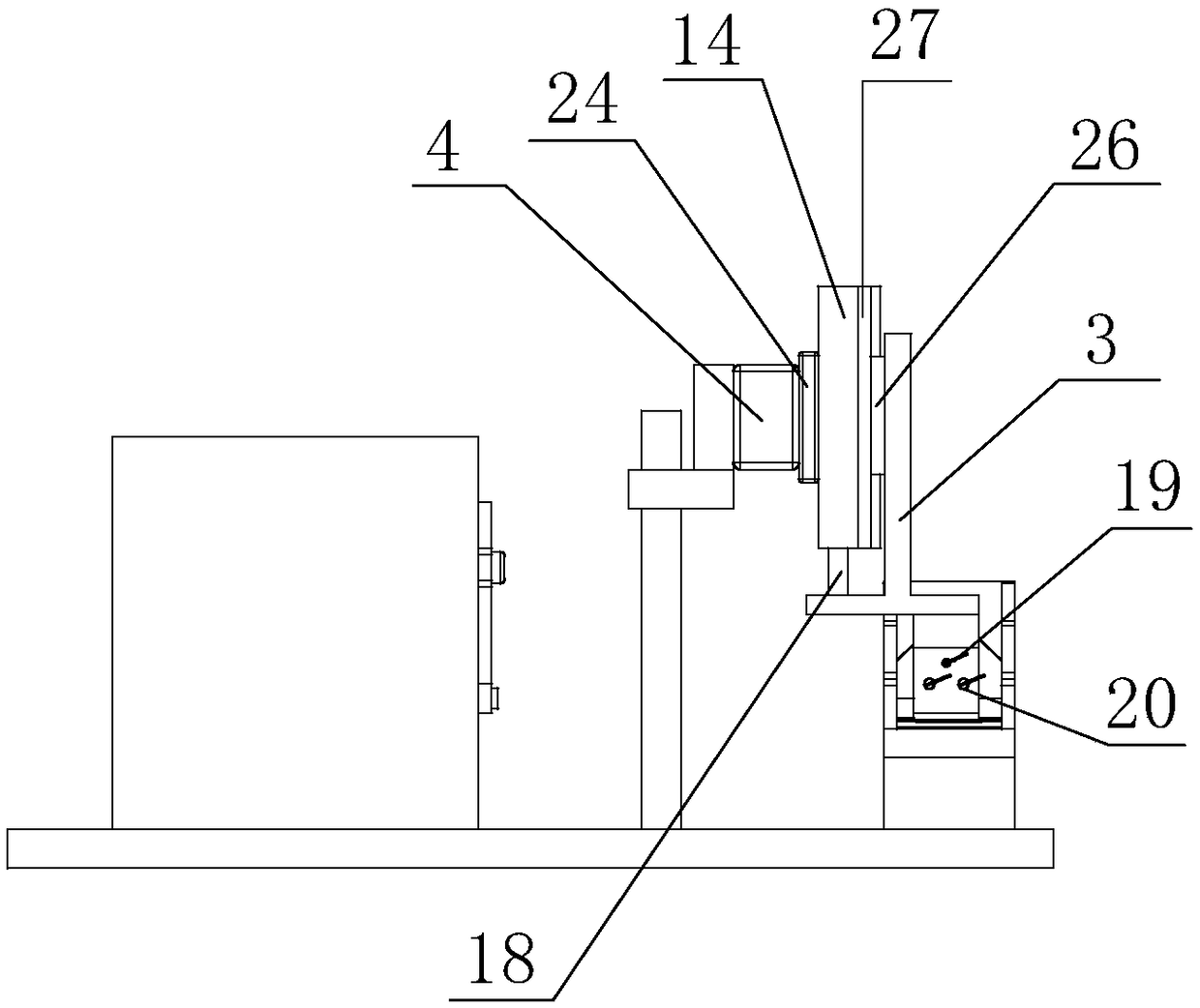
[0035] Figure 1-3 The shown semi-automatic balloon tube preforming machine includes a bottom plate 1, and also includes a moving mechanism, a heating mechanism, and a stretching mechanism; the moving mechanism, the heating mechanism, and the stretching mechanism are all arranged on the bottom plate 1;
[0036] The moving mechanism is arranged in the middle of the bottom plate 1; the moving mechanism includes a rear support frame 12 and a front support frame 3; the rear support frame 12 is fixedly arranged on the bottom plate 1; the upper end of the front side of the rear support frame 12 is provided with a moving motor 4 and a moving motor 4 A lifting cylinder 14 is provided on the front side of the moving motor 4; further, a moving sliding table 24 is provided on the front side of the moving motor 4, and the moving sliding table 24 can move laterally u...
PUM
 Abstract
Description
Claims
Application Information