A surface knocking device for mechanical parts of construction equipment
What is Al technical title?
Al technical title is built by PatSnap Al team. It summarizes the technical point description of the patent document.
A technology for mechanical parts and construction equipment, which is applied in the field of surface percussion devices for mechanical parts of construction equipment, can solve the problems of inconvenient percussion positions, processing, adjustment, etc., and achieve rigid structures, improved practicability, and uniform percussion Effect
Active Publication Date: 2020-03-17
温州洪升建筑机械有限公司
View PDF5 Cites 0 Cited by
Summary
Abstract
Description
Claims
Application Information
AI Technical Summary
This helps you quickly interpret patents by identifying the three key elements:
Problems solved by technology
Method used
Benefits of technology
Problems solved by technology
[0002] In the process of processing some construction equipment, it is necessary to knock and beat the surface of the workpiece to improve the durability and mechanical properties of the workpiece. The existing knocking device is not convenient for adjusting the position of the knocking, and it is not convenient for different Repeated knocking on the workpiece cannot improve the knocking efficiency. There is a problem that the structure of the knocking device is rigid. Can be processed for different workpiece shapes, reducing the practicability of the knocking device
Method used
Image
Click on the blue label to locate the original text in one second.
Reading with bidirectional positioning of images and text.
Examples
Embodiment Construction
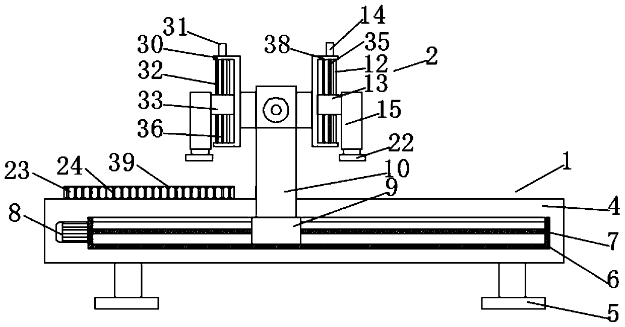
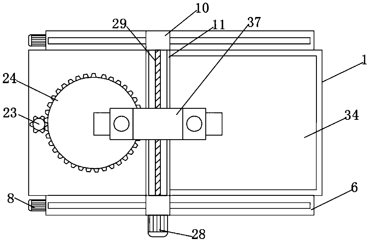
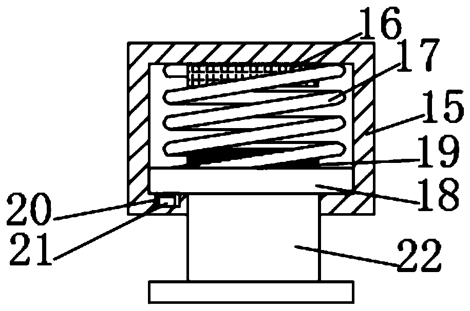
[0020] Such as Figure 1-4 As shown, this specific embodiment adopts the following technical solutions: a surface knocking device for mechanical parts of construction equipment, including a supporting mechanism 1, a knocking mechanism 2 and a rotating mechanism 3, and the top of the supporting mechanism 1 is provided with a rotating mechanism 3 , the top of the support mechanism 1 is provided with a knocking mechanism 2, and the support mechanism 1 is composed of a workbench 4, a fixed pillar 5, a moving chute 6, a moving screw mandrel 7, a moving motor 8, a moving slider 9, and a driving gear 23. The external ring gear 24, the rotating shaft 25, the rotating motor 26, the reducer 27 and the adjusting motor 28 are composed of a moving chute 6 which is symmetrically and fixedly connected to the outside of the workbench 4, and the inside of the moving chute 6 is slidingly connected with Moving slide block 9, the inside of described moving slide block 9 is connected with moving s...
PUM
Abstract
The invention discloses a surface knocking device for mechanical components of building equipment. The surface knocking device comprises a support mechanism, a knocking mechanism and a rotary mechanism. The rotary mechanism is arranged on the top of the support mechanism, the knocking mechanism is arranged above the support mechanism, the support mechanism comprises a worktable, fixing props, movable slide grooves, movable lead screws, movable motors, a movable slider, a driving gear, an outer gear ring, a rotary shaft, a rotary motor, a speed reducer and an adjusting motor, and the movable slide grooves are symmetrically fixedly connected with the outer side of the worktable. The surface knocking device has the advantages that the surface knocking device is provided with the adjusting motor, accordingly, knocking columns can conveniently move, different workpieces can be conveniently repeatedly knocked, the time and labor can be saved, the knocking efficiency can be improved, and theproblem of inflexible structures of existing knocking devices can be solved by the aid of the surface knocking device; the surface knocking device is provided with a rotary disc, the circular workpieces can rotate by the aid of the rotary motor, can be simultaneously conveniently knocked by the aid of the rotary motor and can be uniformly knocked, the shapes of the different workpieces can be pertinently machined, and accordingly the practicality of the surface knocking device can be greatly improved.
Description
Technical field: [0001] The invention relates to the technical field of construction machinery, in particular to a surface knocking device for mechanical parts of construction equipment. Background technique: [0002] In the process of processing some construction equipment, it is necessary to knock and beat the surface of the workpiece to improve the durability and mechanical properties of the workpiece. The existing knocking device is inconvenient to adjust the position of the knock, and it is not convenient to adjust the position of the different parts. Repeated knocking on the workpiece cannot improve the knocking efficiency. There is a problem that the structure of the knocking device is rigid. It can be processed for different workpiece shapes, which reduces the practicability of the knocking device. Invention content: [0003] The purpose of the present invention is to provide a surface knocking device for mechanical parts of construction equipment in order to solv...
Claims
Application Information
Patent Timeline
Application Date:The date an application was filed.
Publication Date:The date a patent or application was officially published.
First Publication Date:The earliest publication date of a patent with the same application number.
Issue Date:Publication date of the patent grant document.
PCT Entry Date:The Entry date of PCT National Phase.
Estimated Expiry Date:The statutory expiry date of a patent right according to the Patent Law, and it is the longest term of protection that the patent right can achieve without the termination of the patent right due to other reasons(Term extension factor has been taken into account ).
Invalid Date:Actual expiry date is based on effective date or publication date of legal transaction data of invalid patent.