
Filter

A filter and filter element technology, which is applied in the direction of filtration loop, filtration separation, dispersed particle filtration, etc., can solve the problems of increased fluid resistance and poor flow state.

Active Publication Date: 2019-01-29
JIANGXI HONGDU AVIATION IND GRP
View PDF8 Cites 2 Cited by
  • Summary
  • Abstract
  • Description
  • Claims
  • Application Information

AI Technical Summary

Problems solved by technology

[0003] At present, the filter technology for coarse filtration is relatively mature, but fine filtration requires an extremely fine filter mesh, which will increase the resistance of the fluid and deteriorate the flow state

Method used


Image

  • Filter

Examples


Embodiment Construction

[0017] In order to make the purpose, technical solutions and advantages of the embodiments of the present invention more clear, the technical solutions in the embodiments of the present invention will be clearly and completely described below in conjunction with the drawings in the embodiments of the present invention. Apparently, the described embodiments are some, but not all, embodiments of the present invention. Based on the embodiments of the present invention, all other embodiments obtained by persons of ordinary skill in the art without making creative efforts belong to the protection scope of the present invention.

[0018] Features and exemplary embodiments of various aspects of the invention are described in detail below. In the following detailed description, numerous specific details are set forth in order to provide a thorough understanding of the present invention. It will be apparent, however, to one skilled in the art that the present invention may be practice...


PUM


Abstract

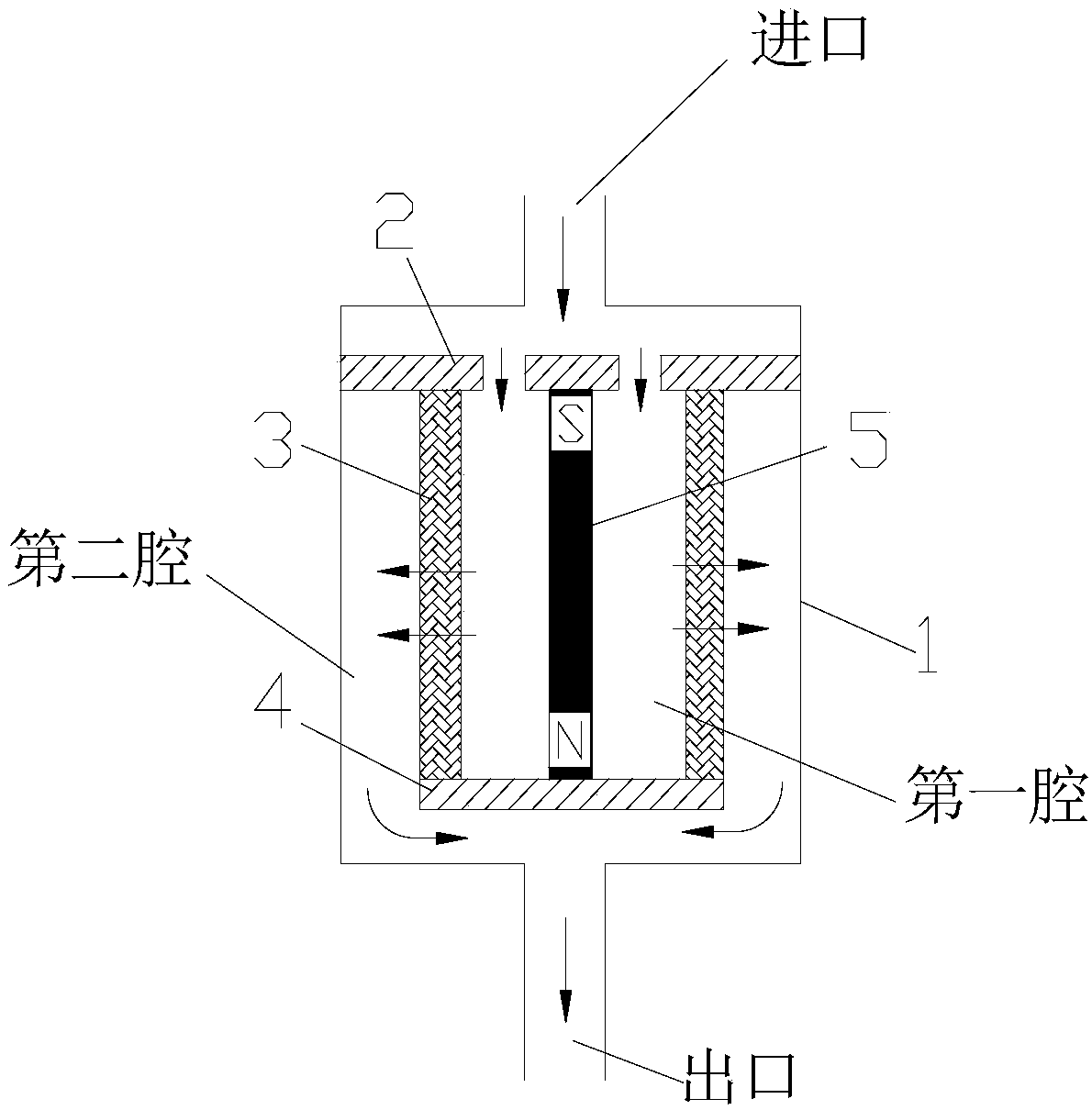
The invention provides a filter. The filter comprises a shell, an upper support plate, a filter element, a lower support plate and a magnetic core. The filter element is fixed and installed in the shell by the upper support plate and the lower support plate. The filter element, the upper support plate and the lower support plate form a first cavity, and the magnetic core is installed in the firstcavity, so that a magnetic field exists on the filter element. The shell, the filter element, the upper support plate and the lower support plate form a second cavity. An inlet of the filter is in communication with the first cavity of the shell, and an outlet of the filter is in communication with the second cavity of the shell. When fluid flows in from an inlet of the shell, enters the first cavity through a circular hole in the upper support plate, then flows through the filter element into the second cavity, and then flows out of the filter through the outlet, pollutant in the fluid is blocked by the filter element under the action of the magnetic field, and cannot flow out of the filter, and therefore fluid cleaning control is realized. The filtering effect of the filter can be greatly improved.

Description

technical field [0001] The invention relates to the field of aviation fluid system design, and in particular to filters for fluid cleaning control. Background technique [0002] One of the ways to keep fluid media clean is to use filters. Filters are able to filter out dirt from passing fluid. [0003] At present, the filter technology for coarse filtration is relatively mature, but fine filtration requires an extremely fine filter mesh, which will increase the resistance of the fluid and deteriorate the flow state. Contents of the invention [0004] In view of this, in order to solve at least one technical problem in the prior art, the present invention provides a filter. [0005] The filter includes: a shell, an upper support plate, a filter element, a lower support plate, and a magnetic core, wherein: [0006] The filter element is fixed by the upper support plate and the lower support plate and installed in the housing; [0007] The filter element, the upper suppor...

Claims


Application Information

Patent Timeline
Patent Type & Authority Applications(China)
IPC IPC(8): B03C1/30B01D36/00B01D46/00
CPCB01D36/00B01D46/0034B03C1/30
Inventor 周昌申赵胜海郭祥天杨佳明阙胜才田瑞娟张艳李涛龙海燕汪海欧军王辉周伊优姚雅琳
Owner JIANGXI HONGDU AVIATION IND GRP
Learn More