Cold storage condensate device

A technology of condensed water and cold storage, which is applied in the direction of refrigerators, refrigeration and liquefaction, and the operation mode of machines, etc. It can solve problems such as difficult to achieve condensation dehumidification temperature, slow water condensation speed, low humidity, etc., and achieve electronic precision Dehumidification, increase the effective space, and ensure the effect of airtightness

Inactive Publication Date: 2018-06-22
DONGGUAN LVKON ELECTRICAL TECH CO LTD
View PDF8 Cites 0 Cited by
  • Summary
  • Abstract
  • Description
  • Claims
  • Application Information

AI Technical Summary

Problems solved by technology

[0005] 1. The power consumption of refrigeration is large, resulting in a large energy consumption in the refrigeration and dehumidification process;
[0006] 2. Since the dehumidification cooling plate is installed on the back wall of the moisture-proof box, the outside does not have an insulating environment. Therefore, in the process of cooling and dehumidification, the air in the sealed box is also refrigerated. The air is refrigerated and the upper hot air is replenished, resulting in The temperature of the gas in the sealed box space drops, and the distance between water molecules shrinks, which leads to a slowdown of the condensation rate, and at the same time, increases the power consumption of dehumidification, but it is difficult to achieve the ideal condensation dehumidification temperature on the cooling and dehumidification fins;
[0007] 3. For the cold dehumidifier used in the moisture-proof box, because the speed of water condensation is too low, it cannot form enough water droplets to fall, but sticks to the heat sink. After the cooling stops, the water disperses again, resulting in water Cannot be discharged into the moisture-proof box;
[0008] 4. In the case of low ambient temperature, the working efficiency of this condensing dehumidifier will be greatly reduced
[0009] 5. The condensed water used in the traditional technology flows into the water-absorbing sponge below, and then the water is drawn out of the box by the water-absorbing sponge to evaporate. In this process, the water absorbed by the water-absorbing sponge may evaporate outside the box, because part of it is also inside the box. , so, it is also possible to evaporate in the box, causing the water to be unable to be discharged out of the box;
[0010] 6. Due to the structural limitation of the back-mounted type, the dehumidifier will use part of the space in the box;
[0011] It can be seen that the efficiency of the traditional refrigeration type moisture-proof box is very low, and it is difficult to achieve lower humidity, and the dehumidification effect is difficult to meet the actual dehumidification needs

Method used


Image

  • Cold storage condensate device
  • Cold storage condensate device
  • Cold storage condensate device

Examples


specific Embodiment 1

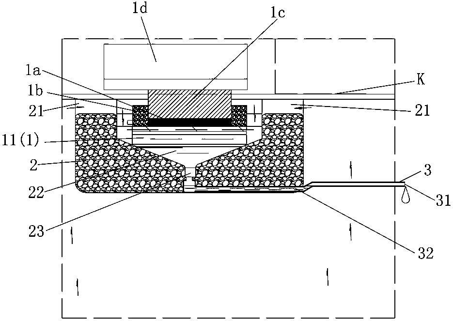
[0039] Such as Figure 1-5 As shown, the present invention relates to a cold storage condensate device, which includes a refrigeration unit 1, which is used to condense water molecules in the air. The refrigeration unit 1 includes a refrigeration body 11, and the refrigeration body 11 is arranged in a In the heat-insulation shell 2, the heat-insulation shell 2 is used to hold condensed water, and the water vapor inlet 21 is arranged on the heat-insulation shell 2, and a drain pipe 3 is arranged at the bottom of the heat-insulation shell 2, and the drain pipe 3 is used for Drain the condensed water in the heat-insulating shell, and the drain pipe 3 communicates with the heat-insulating shell 2 .

[0040] Such as Figure 1-2 As shown, the insulated housing 2 is concavely formed with a groove 22, which is used to set the cooling body 11. The groove 22 is funnel-shaped, and the edge of the groove wall of the groove 22 is higher than the highest cooling capacity of the cooling bod...

specific Embodiment 2

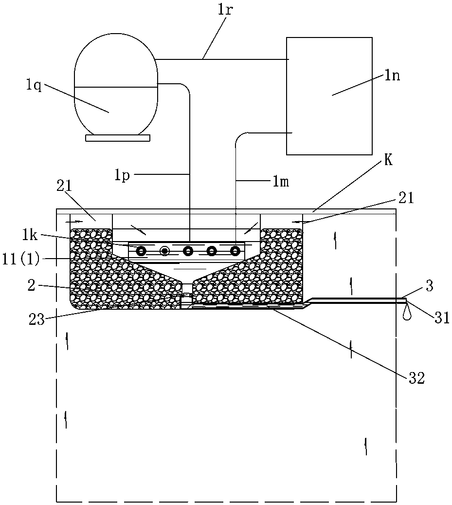
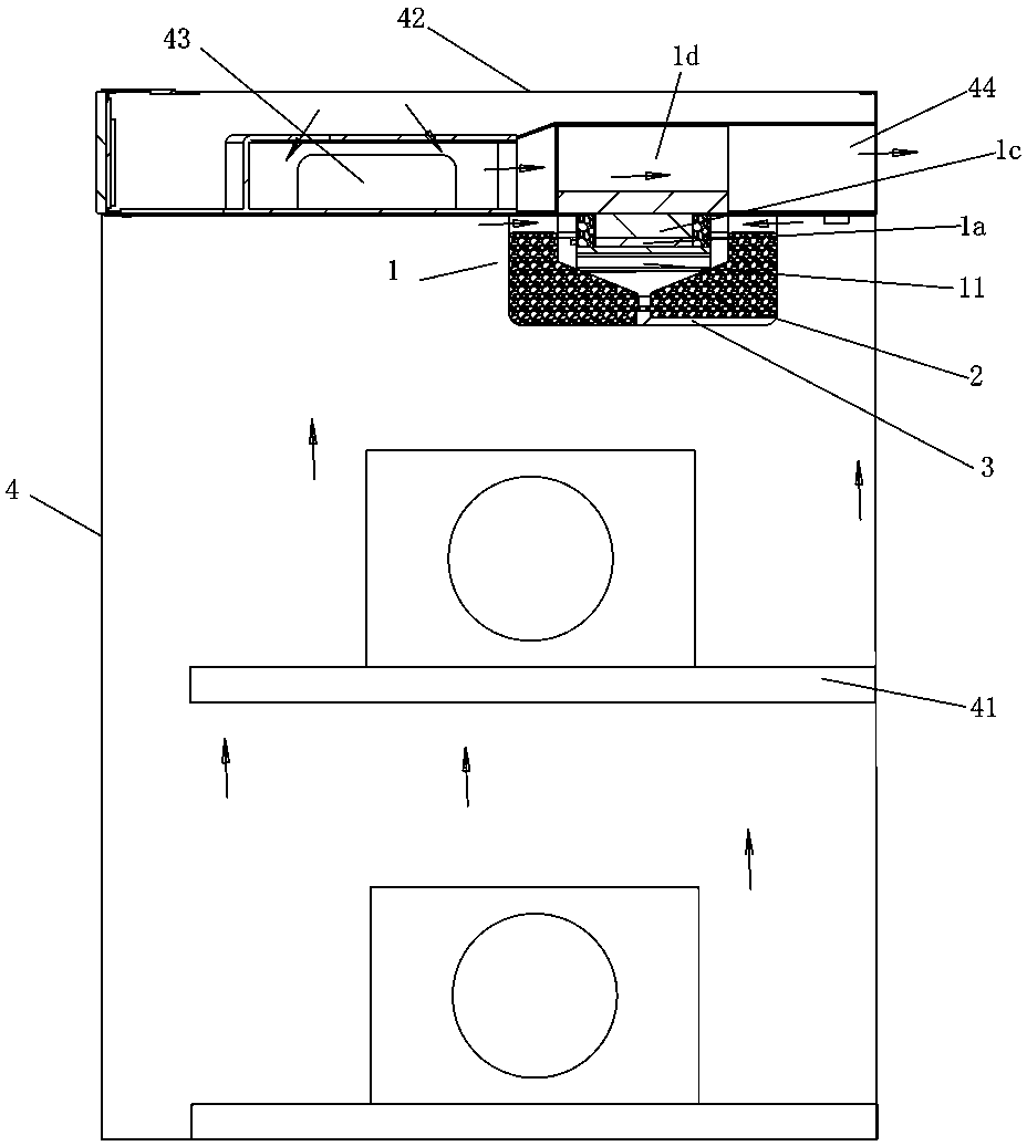
[0048] Such as image 3 As shown, a cold storage condensate device disclosed by the present invention, the dehumidifier can be installed in the moisture-proof box 4, and the moisture-proof box 4 is also provided with a number of shelves 41, and each of the shelves 41 is used to place moisture-proof Items, the insulation shell 2 of the dehumidifier is provided with a partition K, the partition K is the top plate of the moisture-proof box 4, a heat dissipation chamber 42 is arranged on the top plate, and the cooling body 11 of the refrigeration unit 1 of the dehumidifier is A condensing fin, the middle part of the upper surface of the refrigeration body 11 is provided with an electronic refrigeration sheet 1a, and an insulation layer 1b is provided on the outside of the electronic refrigeration sheet 1a. The refrigeration unit 1 also includes a heat dissipation fin 1d, and the heat dissipation fin 1d passes through a The conduction heat dissipation pad 1c passes through the part...

specific Embodiment 3

[0049] Such as Figure 4 As shown, a cold storage condensate device disclosed in the present invention, the dehumidifier can be installed in a wardrobe 5, the wardrobe 5 is composed of an upper cabinet 51 and a lower cabinet 52, and the dehumidifier is located in the lower cabinet 52 Near the top surface, the refrigeration body 11 of the refrigeration unit 1 of the dehumidifier is a condensing fin, and the middle part of the upper surface of the refrigeration body 11 is provided with an electronic refrigeration sheet 1a, and an insulation layer 1b is provided on the outside of the electronic refrigeration sheet 1a. The upper surface of the electronic cooling plate 1a is connected to at least one water-cooled heat exchanger 1e, and the water-cooled heat exchanger 1e is connected to a water-cooled radiator 1g through a first circulating water pipe 1f, and the water-cooled radiator 1g passes through a second circulation The water pipe 1h is connected to a water pump 1i, and the w...


PUM


Abstract

The invention relates to the technical field of dehumidification equipment for moisture-proof boxes and discloses a cooling storage type condensation water device. The cooling storage type condensation water device comprises a refrigerating unit. The refrigerating unit is used for condensing water molecules in air and comprises a refrigerating body inside. The refrigerating body is arranged in a thermal insulating shell. The thermal insulating shell is used for containing condensed water and provided with water vapor inlets. A water discharging pipe is arranged at the bottom of the thermal insulating shell and used for discharging the condensed water in the thermal insulating shell. The water discharging pipe is communicated with the thermal insulating shell. According to the cooling storage type condensation water device, the refrigerating energy consumption is greatly reduced; the effective space inside a sealed box body is greatly enlarged; stored materials in a sealed space is not refrigerated; the secondary evaporation probability of the condensed water is greatly lowered, and the condensed water during dehumidification can flow out smoothly; the low-temperature dehumidification effect and the electronic precise dehumidification are effectively achieved; the tightness of the box body is ensured.

Description

technical field [0001] The invention relates to the technical field of distillation and dehumidification equipment, in particular to a cold-storage condensed water device that prevents stored items from being refrigerated through a heat-insulating shell. Background technique [0002] In a space that can ensure airtightness, use dehumidification and dehumidification technology that can effectively reduce the original moisture in a specific capacity space, so as to achieve the required functions such as moisture resistance, mildew resistance, oxidation resistance, rust prevention, deterioration prevention, and qualitative change prevention. Such boxes and cabinets are called moisture-proof boxes or moisture-proof cabinets. [0003] In addition, in the existing condensation technology, the method of flowing air distillation is adopted. In this way, the air brings a lot of heat, and most of the cooling power is occupied by the heat in the air, and a small part of the power is ta...

Claims


Application Information

Patent Timeline
Patent Type & Authority Patents(China)
IPC IPC(8): F25B21/00
CPCF25B21/00Y02B30/00
Inventor 倪军
Owner DONGGUAN LVKON ELECTRICAL TECH CO LTD
Why Eureka
Try Eureka