Supercharge Your Innovation With Domain-Expert AI Agents!

Net release machine with rotating tray

A rotating material tray with self-contained technology, applied in the field of net release machine, can solve the problems that the clamping device cannot get the material, the whole net release machine cannot work normally, etc., and achieve the effect of accurate positioning of the material.

Active Publication Date: 2021-08-24
秦皇岛联智科技有限公司
View PDF0 Cites 0 Cited by
  • Summary
  • Abstract
  • Description
  • Claims
  • Application Information

AI Technical Summary

Problems solved by technology

[0003] The purpose of the present invention is to provide a net unwinding machine with its own rotating material tray, aiming at the problem that the clamping device of the net unwinding machine in the prior art sometimes cannot get the material, so that the entire net unwinding machine cannot work normally.

Method used


Image

  • Net release machine with rotating tray
  • Net release machine with rotating tray
  • Net release machine with rotating tray

Examples


Embodiment Construction

[0026] The present invention will be further described below in conjunction with specific embodiment:

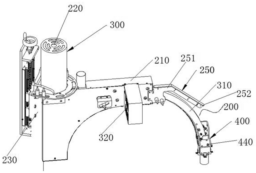
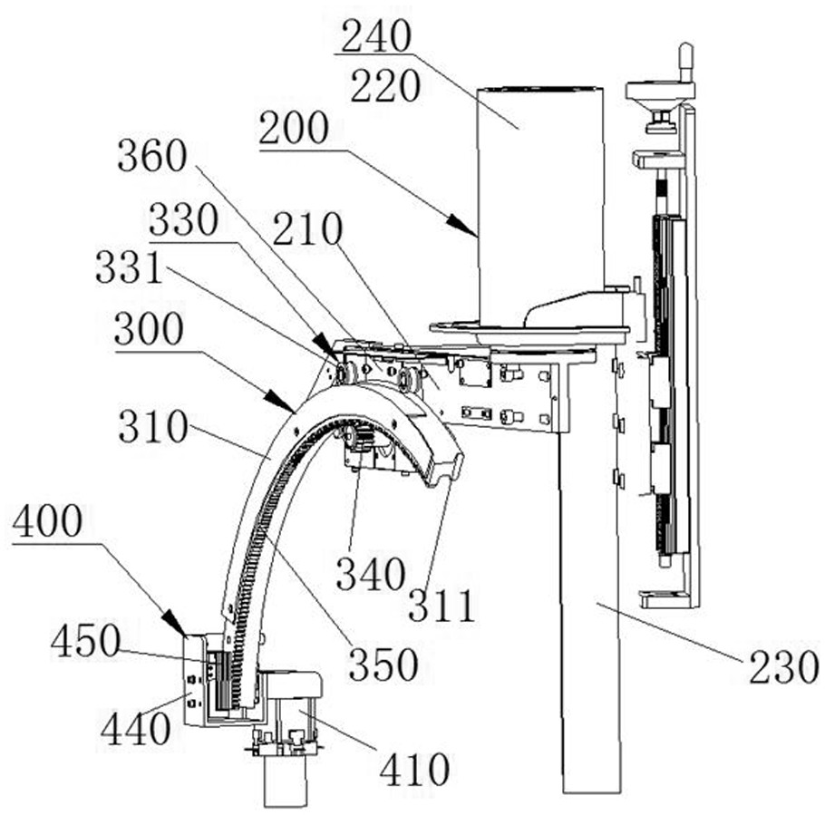
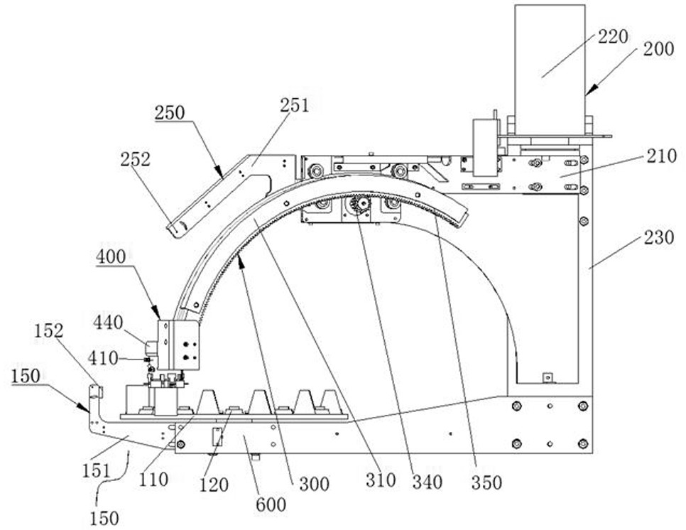
[0027] Such as Figure 1 to Figure 5 As shown, a net unwinding machine with a rotating tray includes an up and down swing device 300 and a left and right swing device 200 , a rotary feeding device 100 , a material detection device 150 and a clamping device 400 .

[0028] The left and right swing device 200 includes a swing frame 210 , the vertical swing device 300 is fixedly arranged on the swing frame 210 , and the clamping device 400 is fixedly connected to the output end of the vertical swing device 300 .

[0029] Such as image 3 combine Figure 5 As shown, the rotary feeding device 100 includes a swinging material device 160 and a driving device 130. The swinging material device 160 includes a rotating material tray 110 and a material positioning block 120. The upper end surface of the rotating material tray 110 is distributed with a plurality of material positioning ...


PUM


Abstract

The present invention aims at the deficiency that the clamping device of the net unwinding machine in the prior art sometimes cannot get the material, so that the whole net unwinding machine cannot work normally, and provides a net unwinding machine with its own rotating material tray. This net unwinding machine includes upper and lower Swing device and left and right swing device, rotary feeding device, material detection device 1 and clamping device, rotary feeding device includes swinging device and driving device 3, swinging device includes rotating material tray and material positioning block, the upper end surface of rotating material tray There are a plurality of material positioning blocks distributed along its edge. Using the net unwinding machine with its own rotating tray provided by the present invention, the retrieving device can repeatedly reclaim materials at the same position, so the retrieving positioning is accurate, and the next material is positioned The block rotates until it is detected that there is material on the rotating material positioning block, so as to ensure that when the material clamping device grabs the material, there is material on the material positioning block, so as to avoid that the clamping device cannot be grasped due to the lack of material on the material positioning block materials.

Description

technical field [0001] The invention relates to a net releasing machine with a rotating material tray. Background technique [0002] In the automotive wheel manufacturing plant, the placement of cast wheel center screens is usually done by a screen laying machine. The net unwinding machine in the prior art generally includes an up and down swing device and a left and right swing device. The up and down swing device adjusts the up and down position of the grabbing device, and the left and right swinging device adjusts the left and right positions of the grabbing device, and the material is taken by the clamping device. The above structure is adopted For the unwinding machine, because the clamping device needs to pick up the material at different positions, the accuracy of the picking is low, and the picking device may not be able to clamp the material, so it may cause empty material feeding, so that the whole device cannot work normally. Contents of the invention [0003] ...

Claims


Application Information

Patent Timeline
Patent Type & Authority Patents(China)
IPC IPC(8): B65G47/82B65G47/90B65G43/08
CPCB65G43/08B65G47/82B65G47/90B65G2203/0208B65G2203/042
Inventor 刘正宾石磊王广强唐辉赵春风陈攀峰王军
Owner 秦皇岛联智科技有限公司
Features
  • R&D
  • Intellectual Property
  • Life Sciences
  • Materials
  • Tech Scout
  • Unparalleled Data Quality
  • Higher Quality Content
  • 60% Fewer Hallucinations
Learn More